
Method for vibration-optimizing a machine tool

An optimization method and technology of machine tools, applied in automatic control devices, metal processing mechanical parts, program control, etc., can solve the problems of surface quality deterioration, inaccurate processing, unbalance, etc., and achieve the effect of suppressing resonance and avoiding resonance.

Inactive Publication Date: 2008-05-14
P&L合资有限公司
View PDF0 Cites 11 Cited by
  • Summary
  • Abstract
  • Description
  • Claims
  • Application Information

AI Technical Summary

Problems solved by technology

However, it is not always possible to achieve the desired
Instead, minor residual imbalances can occur, which can also be caused, for example, by clamping of workpieces or tools
The tool or workpiece itself can also cause an imbalance
[0004] Vibration due to imbalance, resulting in inaccurate machining and poor surface quality

Method used


Image

  • Method for vibration-optimizing a machine tool
  • Method for vibration-optimizing a machine tool

Examples


Embodiment Construction

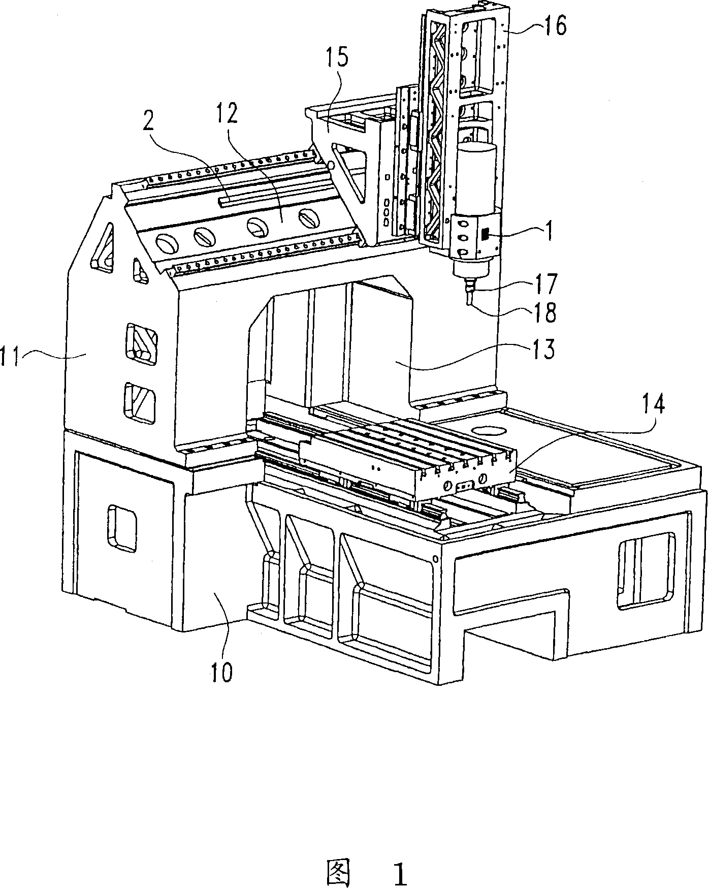
[0030] FIG. 1 shows a machine tool comprising a machine table 10 on which a portal 11 with a cross member 12 is mounted. In the working space 13 formed by the gantry 11, a slide carriage 14 is movable along a horizontal movement axis. The transverse slide 15 is movable relative to the transverse member 12 along another horizontal axis. The transverse slide 15 carries a vertical carriage 16 supporting a spindle 17 forming a rotatable shaft, at the end of which a tool 18 is mounted. For the sake of simplicity, the illustration of the fixtures of the tools at the slides has been omitted. The basic structure of the machine tool is known from the prior art, so further explanations are omitted here.

[0031] In the illustrated embodiment, the sensor 1 is mounted on the frame of the main shaft 17 , which sensor is used to detect vibrations of the main shaft 17 .


PUM


Abstract

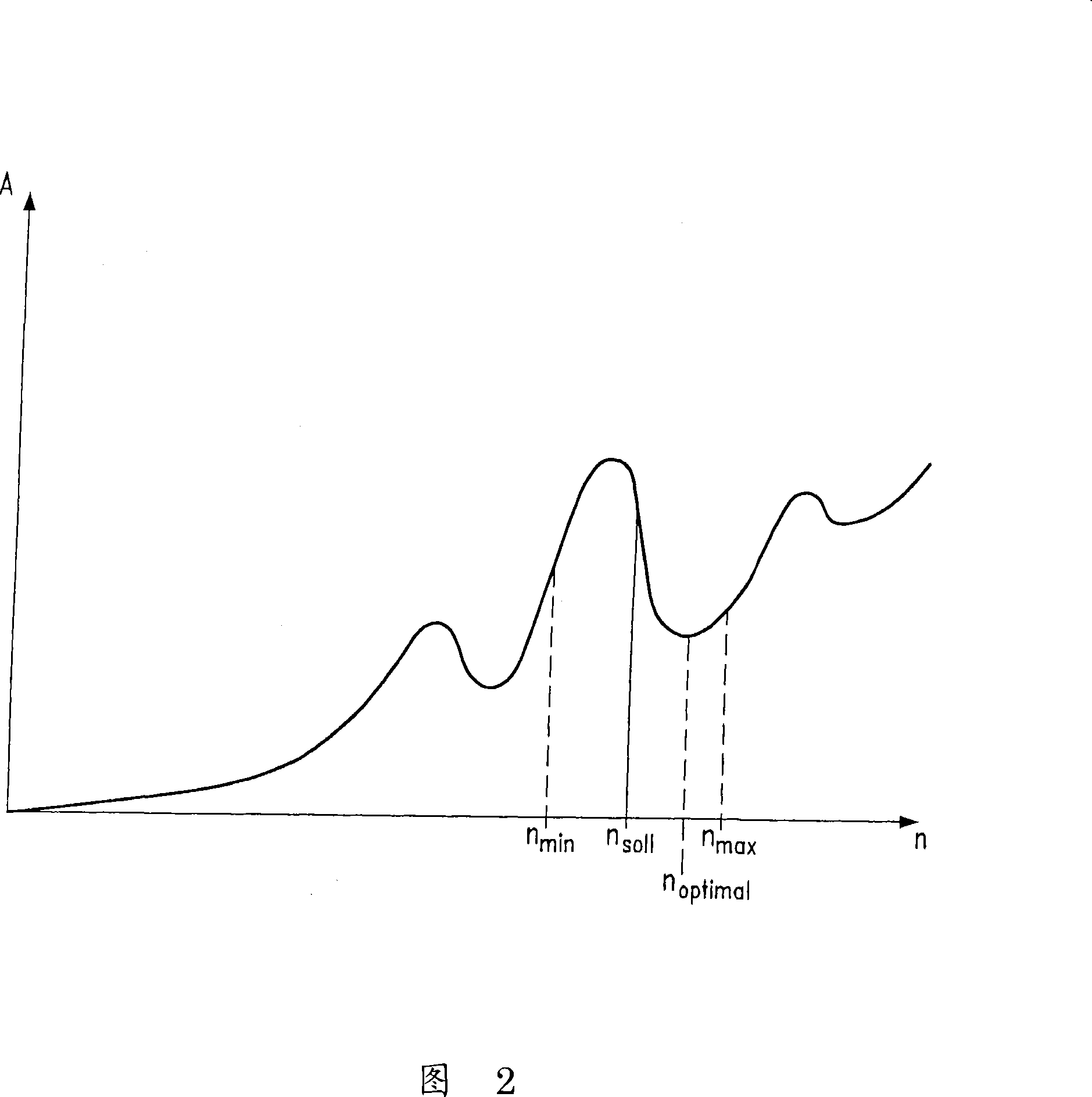
The invention relates to a method for vibration-optimizing a machine tool. The inventive method is characterized by setting a driven shaft (17) rotating, and then covering a speed range. The vibrations produced in the speed range are measured and an optimum speed having a minimum vibration is determined and adjusted.

Description

technical field [0001] The invention relates to a method for optimizing machine tool vibration. Background technique [0002] In machine tools, especially in machine tools for machining workpieces, the workpiece or tool is rotated. In the case of a milling machine, the driven shaft supports the tool, while in the case of a lathe, the workpiece is turned respectively. [0003] During high speed machining, speeds in the range of 40000 rpm or higher are used. In order to be able to achieve the desired machining accuracy, the output shaft needs to be balanced as best as possible. However, it is not always possible to achieve the desired level. Instead, minor residual imbalances can occur, which can also be caused, for example, by the clamping of the workpiece or the tool. The tool or workpiece itself can also cause an imbalance. [0004] Due to the imbalance, vibrations are generated, resulting in inaccurate machining and deterioration of surface quality. For this reason, ...

Claims


Application Information

Patent Timeline
IPC IPC(8): B23Q11/00B23Q15/12G05B19/416
CPCB23Q11/0039G05B2219/37435G05B19/404G05B2219/41122B23Q15/12G05B2219/37432G05B19/4163Y10T409/304424Y10T409/307728Y10T408/76Y10T409/304312Y10T409/303752Y10T408/165
Inventor 荣格尔·勒德斯
Owner P&L合资有限公司
Learn More