Frequency stabilized vertical extended cavity surface emitting lasers

A technology of surface emission and extended cavity, applied in the field of light source, can solve the problem of not fully exploiting the benefits of semiconductor lasers

Inactive Publication Date: 2008-05-14
诺瓦光电技术公司
View PDF10 Cites 11 Cited by
  • Summary
  • Abstract
  • Description
  • Claims
  • Application Information

AI Technical Summary

Problems solved by technology

Therefore, the one-sided direct replacement of UHP lamps with semiconductor lasers cannot

Method used


Image

  • Frequency stabilized vertical extended cavity surface emitting lasers
  • Frequency stabilized vertical extended cavity surface emitting lasers
  • Frequency stabilized vertical extended cavity surface emitting lasers

Examples


Embodiment Construction

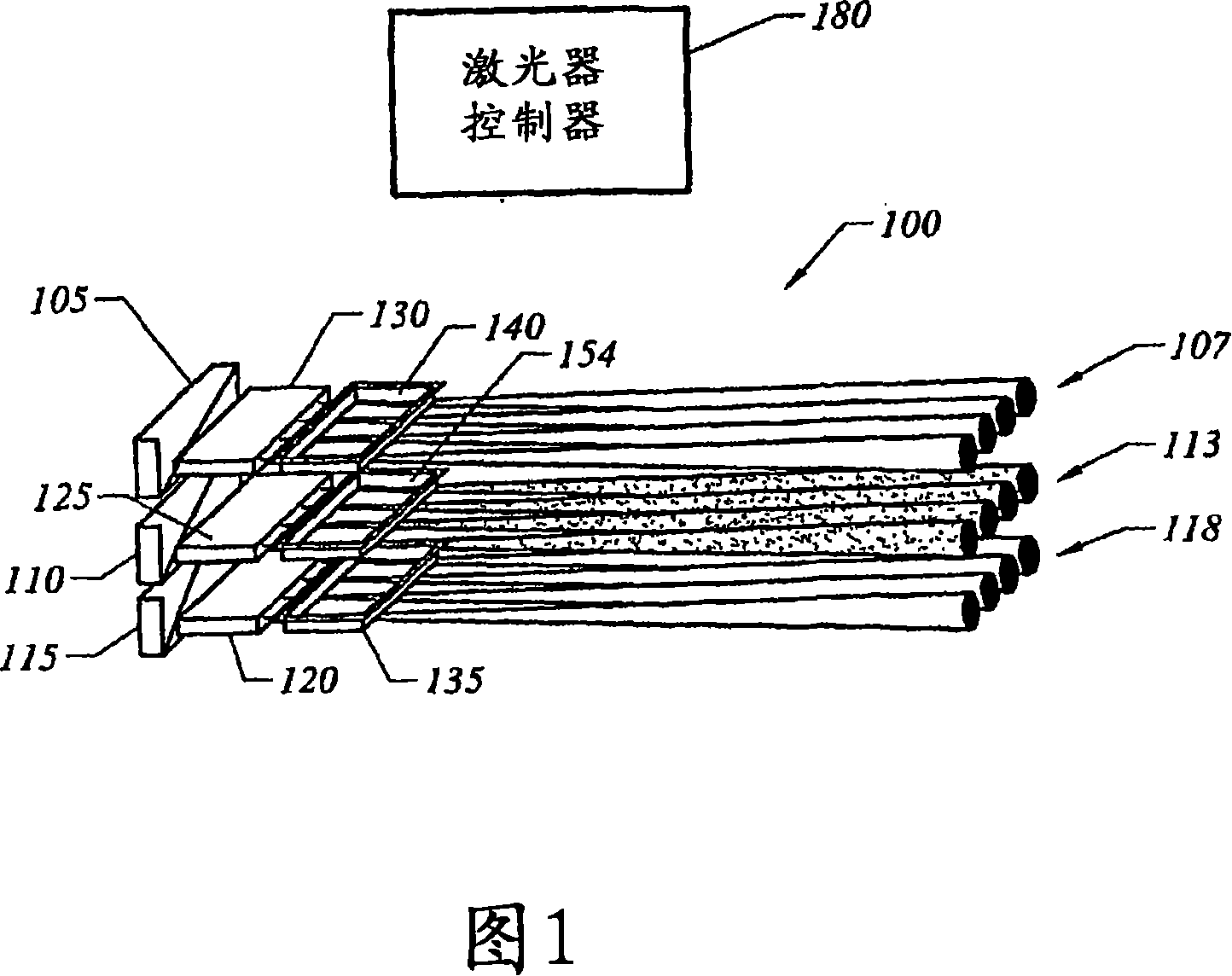
[0060] FIG. 1 is an outline diagram illustrating a light source 100 that produces light of several different colors required by a light processing (LP) system. In a red-green-blue (RGB) LP system, a light source produces red, green, and blue light. A first array 105 of semiconductor lasers is used to generate a plurality of blue light beams 107 from two or more individual lasers. A second array 110 of semiconductor lasers is used to generate a plurality of red light beams 113 from two or more individual lasers. A third array 115 of semiconductor lasers is used to generate a plurality of green light beams 118 from two or more individual lasers. Therefore, the light source 100 comprises different groups of lasers. Individual groups of two or more lasers that produce light of a specific color for an LP system. However, as detailed above, in preferred embodiments, to reduce speckle, individual lasers in a group are designed to be substantially incoherent (eg, out of phase) with...


PUM

PropertyMeasurementUnit
Bandwidthaaaaaaaaaa

Abstract

A vertically extended cavity surface emitting laser (VECSEL) including intracavity frequency doubling. Conventional frequency-controlling elements, such as etalons, are replaced by thin-film interference filters or volume Bragg gratings.

Description

technical field [0001] The present invention generally relates to light sources for use in display systems. In particular, the invention is directed to replacing conventional white light discharge lamps in projection display systems with semiconductor lasers. Background technique [0002] Digital Light Processing (DLP) is of interest for projection display systems, such as systems that project images in conference rooms, home TV systems, advertising displays, automotive dashboards, and heads-up smart displays, among other applications. The light engine of a DLP usually includes a light source and other components required to generate light in several different colors. Components of various colors are spatially modulated, producing individual pixels of selected color intensities. Additional optical elements focus the light on the display. [0003] DLP systems typically include a spatial light modulator that modulates the light source to produce pixels of controlled intens...

Claims


Application Information

Patent Timeline
IPC IPC(8): H01S3/10
CPCG03B21/2033H01S5/4093H01S5/18308H01S5/423G03B21/2013H04N9/315H01S3/08072H04N9/3197H01S5/0071H01S5/4018G03B21/20H01S3/1062G03B21/2073H01S3/109H01S5/18388H01S5/0217H01S5/18305H01S5/141H04N9/3111H01S5/0224H04N9/3129H01S5/02252H01S5/18358H01S5/02326H01S5/0234B82Y20/00G03B21/00G03B21/14G03B21/26
Inventor 安德瑞·V·施彻格诺夫
Owner 诺瓦光电技术公司
Why Eureka
Try Eureka