Novel dynamoelectric concealed mesh window

An invisible screen window and electric technology, which is applied in the direction of windows/doors, door/window protection devices, insect protection, etc., can solve the problems of increasing the size of the motor, unable to roll up, inconsistent, etc., and achieves reduced appearance volume, simple structure, and easy installation convenient effect

Inactive Publication Date: 2008-05-21
周文庆
View PDF2 Cites 12 Cited by
  • Summary
  • Abstract
  • Description
  • Claims
  • Application Information

AI Technical Summary

Problems solved by technology

Among them, the patent No. 95210598.5 of the electric screen window uses a micro-motor to drive the gauze net movement, unless a motor with a larger power is used, but this will increase the volume of the motor and is difficult to be accepted by users.
And the biggest problem of this technical solution is that the gauze is tightened by two pull wires to ensure its smoothness during operation. As the roll-up rod rolls up the gauze, its diameter becomes larger and larger, so every time the roll-up rod rotates, the running distance of the gauze will not be consistent with the length of the pull wire, which will cause the gauze to be too tight to Roll up, or the gauze will lose the tension of the pull wire and become loose and uneven
Although the electric screen window with the patent number 200520043197.3 overcomes this defect, its structure is too complicated, and the many parts will make the use of the electric screen window prone to failure and affect the use of users

Method used


Image

  • Novel dynamoelectric concealed mesh window
  • Novel dynamoelectric concealed mesh window

Examples


Embodiment Construction

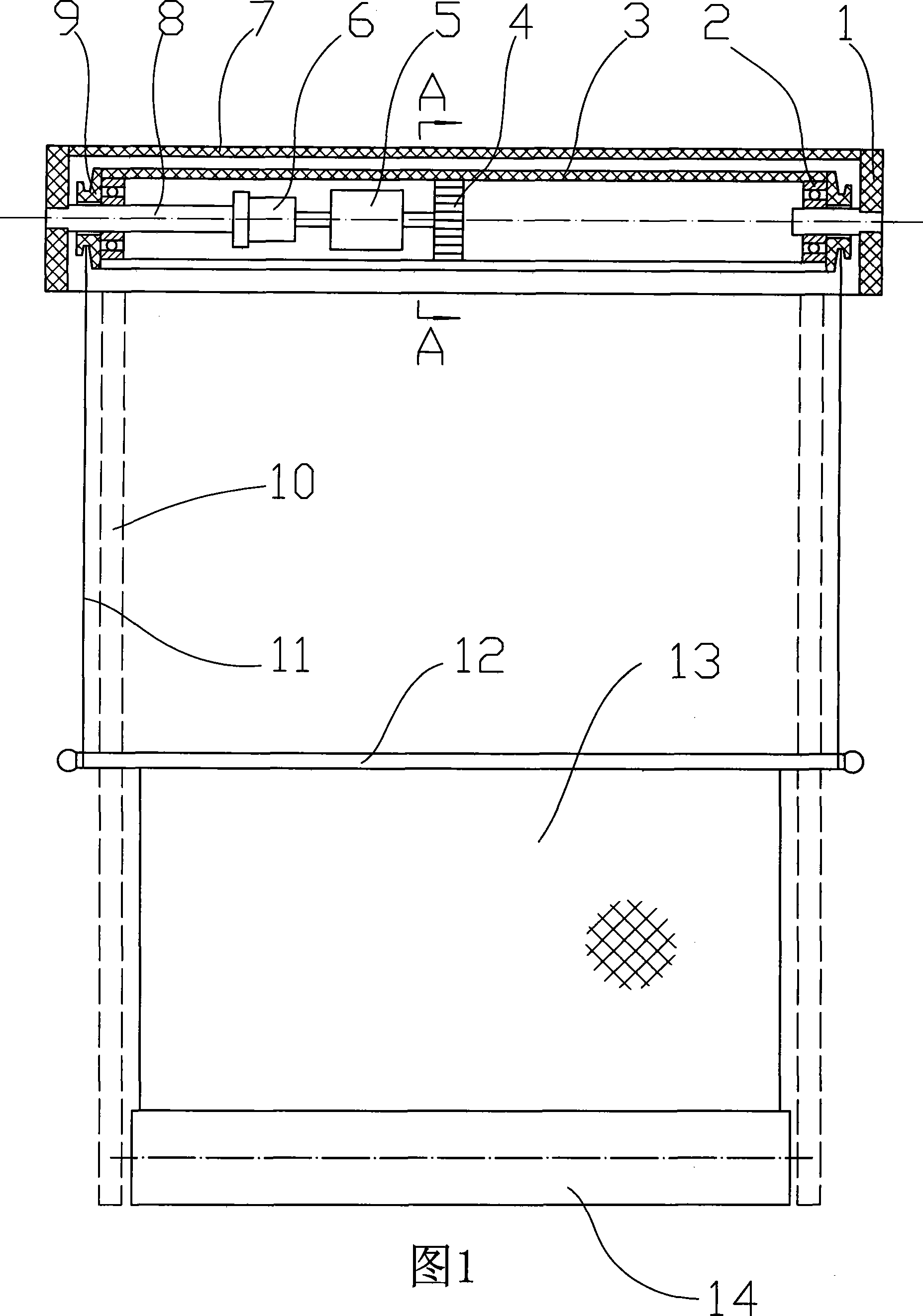
[0016] As shown in Fig. 1 and Fig. 2, the new type electric invisible screen window includes a roller shade cylinder 14 powered by a coil spring, a gauze 13 that can be shrunk in the roller shade cylinder 14, and chute openings on both sides thereof. The frame 10 of the frame, the roller shutter cylinder 14 is located at one end of the two frames 10, and the end of the gauze 13 located outside the roller curtain cylinder 14 is fixed with a tie rod 12. Finally, the two ends of the tie rod 12 are hidden in the two frames 10 .

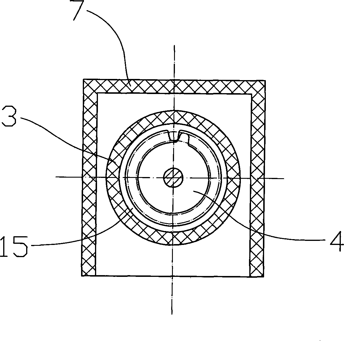
[0017] The other end of the two frames 10 is provided with an electric reel device, which is composed of the outer cover 7 and the reel tube located in the outer cover 7. The reel tube can rotate around its axis under the drive of the motor 6 inside, and its two ends are respectively wound. There is one stay cord 11, and the two stay cords 11 are respectively located on the outer sides of the two frames 10 and connected to the two ends of the tie rods 12 ...


PUM


Abstract

The present invention relates to a novel electric invisible gauze, including a rolling screen cylinder, gauze and a frame. The rolling screen cylinder is arranged at one end of two frames. The end of the gauze arranged at outside of the rolling screen cylinder is fixed with a horizontal pull rod. The other end of the two frames is provided with an electric rolling device including an external housing and a rolling tube in the external housing. The two ends of the rolling tube are rolled with a pull rod respectively. The two pull rods are arranged at the external side of the two frames and connected with the two ends of the horizontal pull rod respectively. The novel electric invisible gauze does not affect the appearance of the window after installation, and has the advantage of simple structure, convenient assembly, reliable use, smooth operation on the gauze and keeping the smooth condition.

Description

technical field [0001] The invention relates to an electric invisible screen window which is driven by a motor to open and close. Background technique [0002] The invisible screen window generally used at present is made up of roller shade cylinder, the gauze that can be crimped in the roller shade cylinder, and the frame that is positioned at its two sides and has chute. The roller shutter tube is installed on the top of the window, the frame is installed on both sides of the window, and the frame is also provided with a draw-in slot communicated with the chute. A tie rod is fixed on the end of the gauze outside the roller blind tube, and the two ends of the tie rod are located in the chute of the two frames. When the screen window is in the open state, the gauze net is curled in the roller blind tube. When the screen window needs to be closed, the tie rod is pulled down by hand to the bottom of the window, and the tie rod is clamped in the slot on the frame. And when th...

Claims


Application Information

Patent Timeline
Patent Type & Authority Applications(China)
IPC IPC(8): E06B9/54E06B9/68
Inventor 周文庆
Owner 周文庆
Why Eureka
Try Eureka