Rod type lens array detecting apparatus and method

A rod lens and detection device technology, applied in the direction of measuring devices, instruments, scientific instruments, etc., can solve the problems of time-consuming, difficult detection, and troublesome comparison and processing of rod lens arrays

Active Publication Date: 2008-05-21
MITSUBISHI CHEM CORP
View PDF1 Cites 8 Cited by
  • Summary
  • Abstract
  • Description
  • Claims
  • Application Information

AI Technical Summary

Problems solved by technology

[0006] However, if this detection method is used, the decrease in the amount of transmitted light and the change in the distribution of light amount will be very small when the irregularities such as blemishes are small, so the difference between the good product judgment standard and the amount of transmitted light etc. is also small, and it is difficult to detect it
Moreover, it is cumbersome to compare the measured light intensity distribution with the preset predetermined light intensity distribution for each rod lens, making the detection of the rod lens array very time-consuming.

Method used


Image

  • Rod type lens array detecting apparatus and method
  • Rod type lens array detecting apparatus and method
  • Rod type lens array detecting apparatus and method

Examples


Embodiment Construction

[0063] Next, an embodiment of the method for manufacturing a rod lens array of the present invention will be described with reference to the drawings.

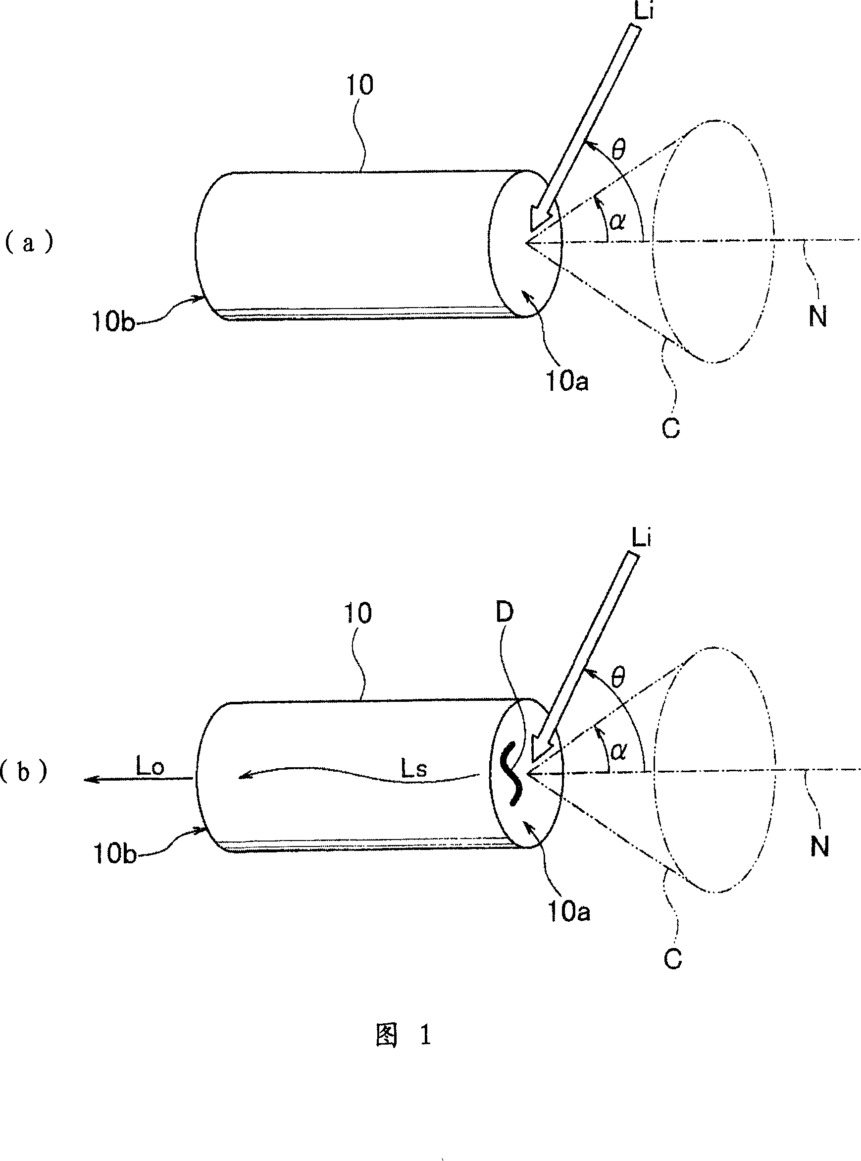
[0064] First, referring to the accompanying drawing 1, the principle of the detection method of the rod lens array of the present invention will be described.

[0065] FIG. 1( a ) and FIG. 1( b ) each typically show a refractive index distribution type rod lens 10 constituting a rod lens array. On the first end face 10a of each rod lens 10, the receiving pyramid C of the rod lens 10 is shown, and the half angle α of the maximum cone angle with respect to the normal N of the end face 10a is also shown.

[0066] The refractive index of the distributed refractive index rod lens 10 has a refractive index distribution that gradually decreases from the central axis toward the outer circular surface.

[0067] The above-mentioned refractive index distribution is on a section perpendicular to the central axis, and when the radius is R...


PUM

PropertyMeasurementUnit
thicknessaaaaaaaaaa
lengthaaaaaaaaaa
lengthaaaaaaaaaa

Abstract

The invention provides a device and a method for detecting whether any irregular factor such as flaw and adhered dirt existed on each stick-type lens end surfaces forming a lens array simply and quickly with high precision. The device comprises a first light source part (2) for irradiating the detection lights on the normal line of the first stick-type lens end surface forming the stick-type lens array (1) with an angle which is larger than the light-receiving angle of the stick-type lens array; a first light-receiving part (3) for detecting the irradiated lights from the second end surface of the stick-type lens array; and a judging part (6) for judging the stick-type lens array (1) as a poor product when the light intensity detected by the light-receiving part (3) exceeds the preset threshold value.

Description

technical field [0001] The present invention relates to a detection device and method for detecting a rod lens array after a plurality of distributed refractive index rod lenses are arranged. A device and a method for attaching irregular factors such as dirt. Background technique [0002] At present, the refractive index distribution type rod lenses that become the light transport path are arranged parallel to each other between two substrates and bonded together as a rod lens array, which is used in various image scanning equipment, copiers, facsimile machines, etc. Optical components used in image sensors, or optical components used in writing devices such as printers are widely used. [0003] Each rod lens constituting the rod lens array is mirror-finished so that both end surfaces become parallel planes perpendicular to the central axis. When there are irregularities such as blemishes and attached dirt on the end faces of the rod lenses, the resolution of the rod lens ...

Claims


Application Information

Patent Timeline
Patent Type & Authority Applications(China)
IPC IPC(8): G01N21/958
Inventor 小池和权犬塚进吾
Owner MITSUBISHI CHEM CORP
Why Eureka
Try Eureka