

LCD device removing ghost
A liquid crystal display and source driver technology, applied in static indicators, instruments, nonlinear optics, etc., can solve problems such as residue, increase system design complexity, and afterimage
- Summary
- Abstract
- Description
- Claims
- Application Information
AI Technical Summary
Problems solved by technology
Method used
Image

Examples
Embodiment Construction
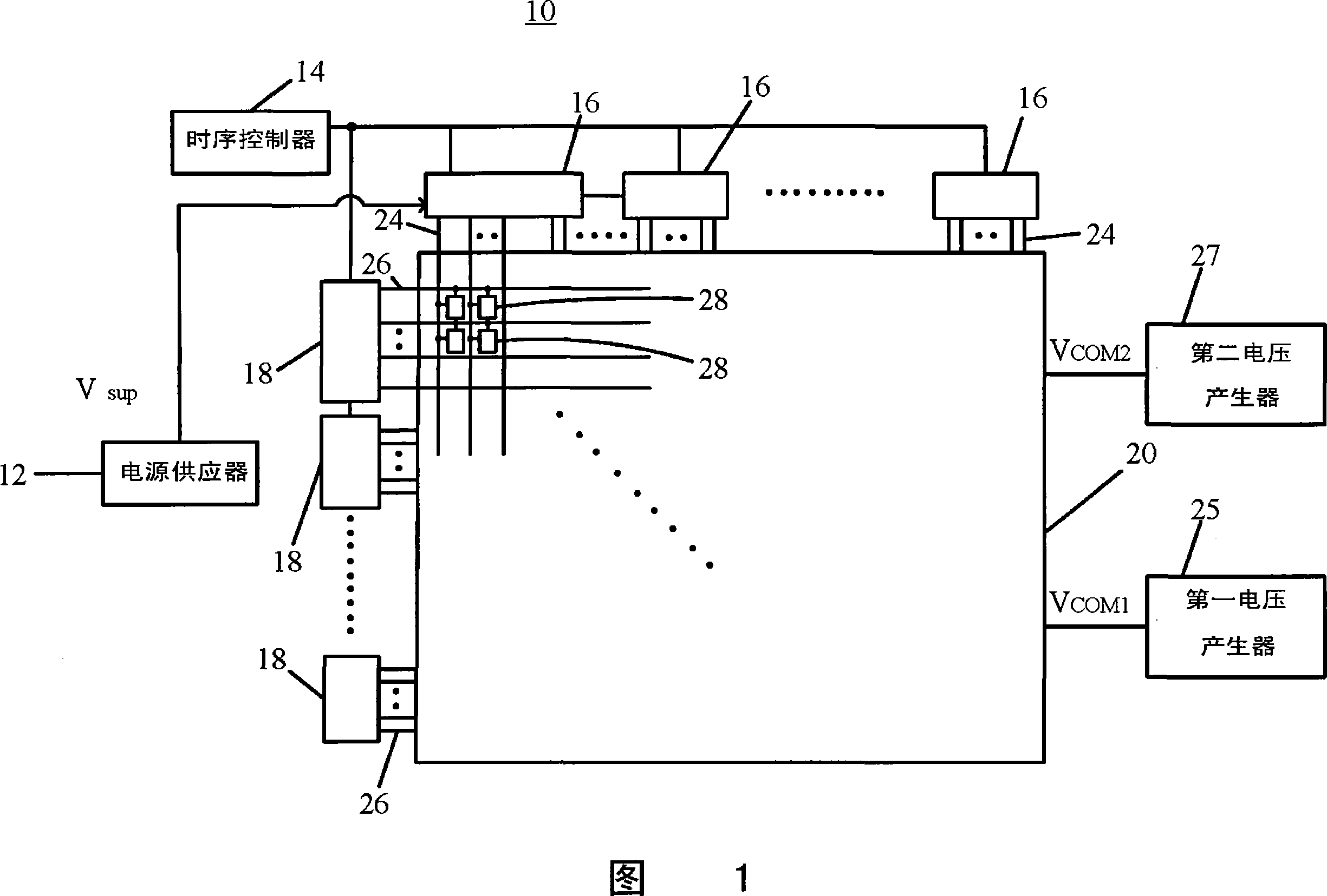
[0014] Please refer to FIG. 1 . FIG. 1 is a functional block diagram of a liquid crystal display of the present invention. The liquid crystal display 10 includes a power supply 12 , a timing controller 14 , a plurality of source drivers 16 , a plurality of gate drivers 18 , a first voltage generator 25 , a second voltage generator 27 and a liquid crystal display panel 20 . The LCD panel 20 includes a plurality of pixel units 28 . The power supply 12 is used to supply the operating voltage Vsup required by all circuits in the liquid crystal display 10 including the timing controller 14 , a plurality of source drivers 16 , and a plurality of gate drivers 18 . For clarity of the drawing, only the connection relationship between the power supply 12 and the plurality of source drivers 16 is shown in FIG. 1 . When the clock signal generated by the timing controller 14 is transmitted to the plurality of gate drivers 18, the plurality of gate drivers 18 will generate scanning signals...
PUM
 Abstract
Description
Claims
Application Information