Installation switching device

A switchgear, terminal technology, applied in the field of installation switchgear, to achieve the effect of avoiding contact, avoiding electrical contact, simplifying insertion and removal operations

Inactive Publication Date: 2011-07-20
ABB PATENT GMBH
View PDF2 Cites 2 Cited by
  • Summary
  • Abstract
  • Description
  • Claims
  • Application Information

AI Technical Summary

Problems solved by technology

The terminal part can only be actuated using an external tool

Method used


Image

  • Installation switching device
  • Installation switching device
  • Installation switching device

Examples


Embodiment Construction

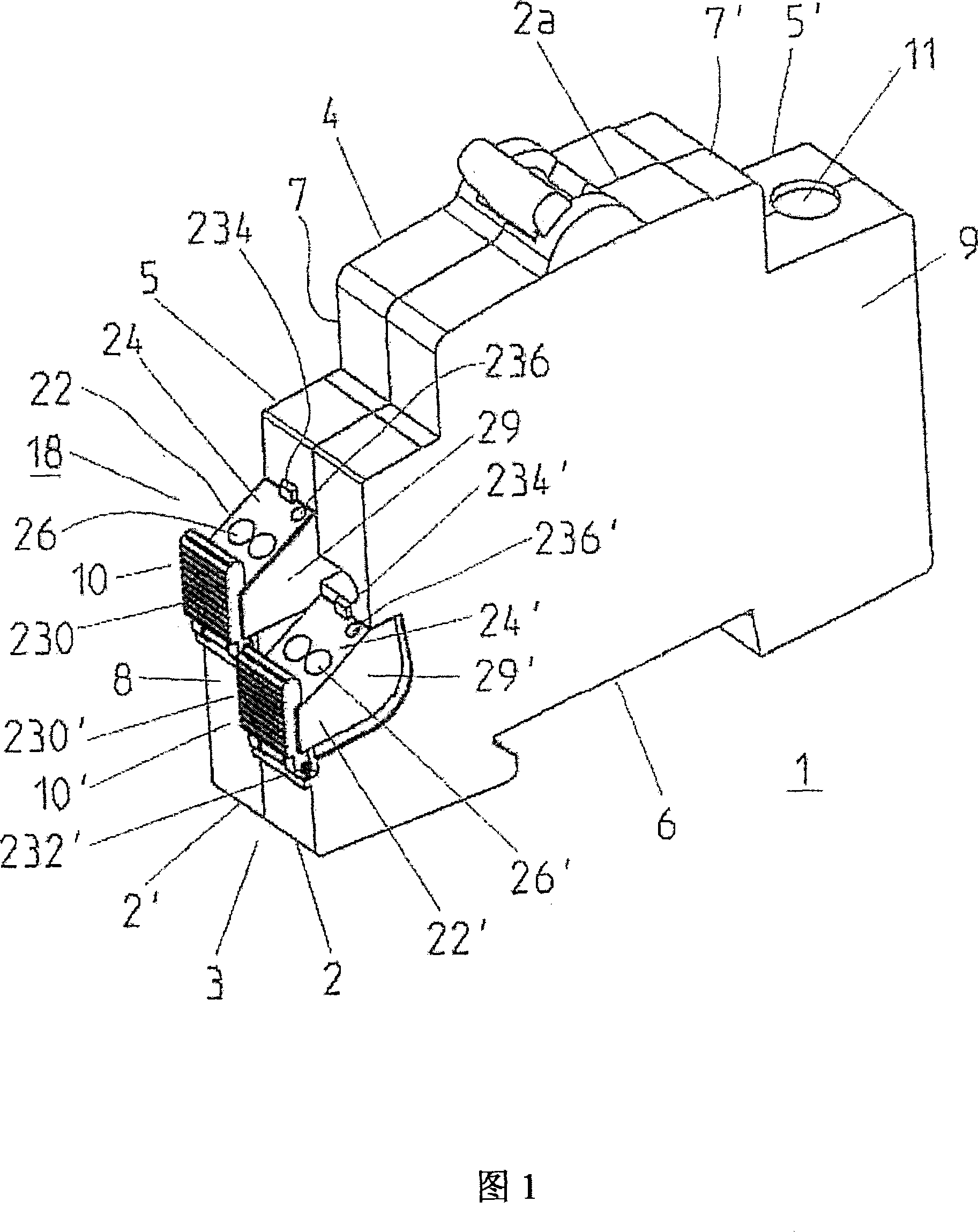
[0165] Think first Figure 1 to Figure 5 . see figure 1 , a mounting switchgear 1 according to the invention has a housing 3 of insulating material formed by joining together two housing parts 2, 2' along a separating plane 2a, the housing 3 having a front side 4, a rear side 5, 5', fixed Or connect side 6, make front side 4 and back side 5,5' connect front narrow side 7,7', back side narrow side 8,8', and two wide sides 9 (in figure 1 Only one of them is shown).

[0166] Attached at the rear 5' in the terminal connection space within the housing 3 is a conventional screw terminal for connecting connecting wires, which is accessible through the terminal opening 11.

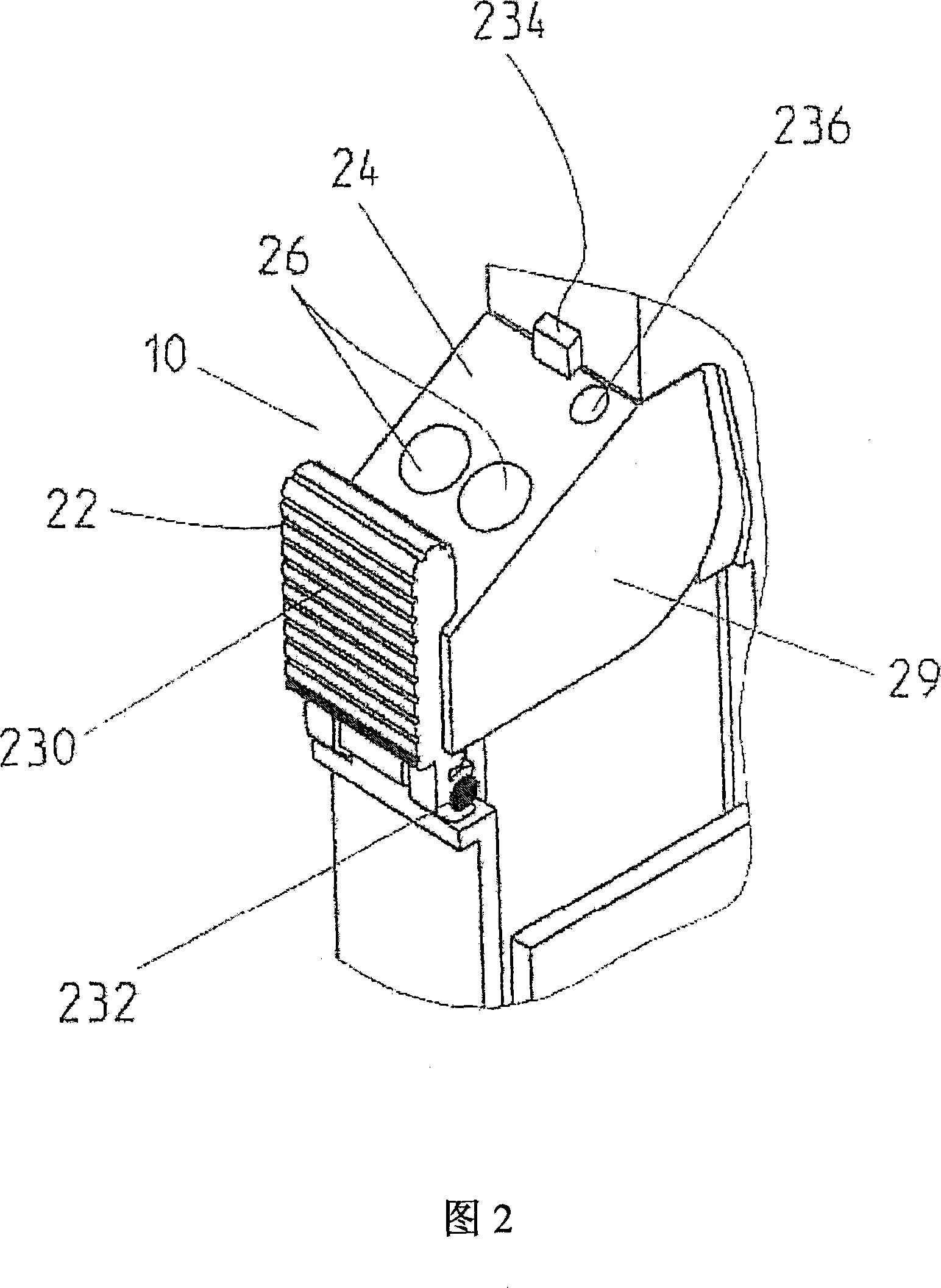
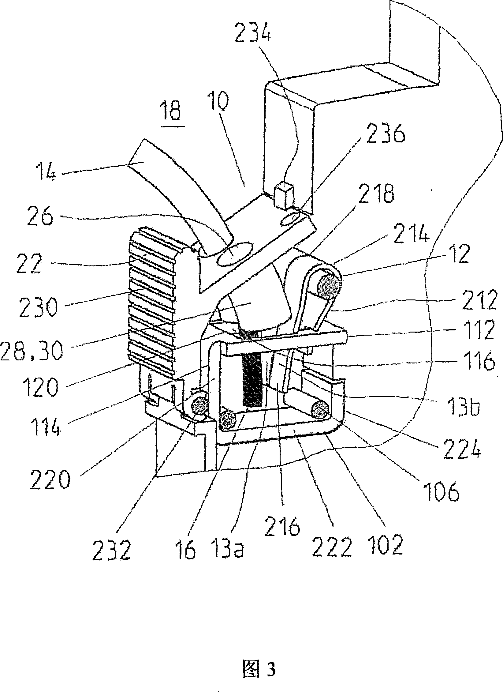
[0167] At the second rear side 5 , opposite the screw terminals, a terminal connection space 18 is provided, wherein the opening of the terminal connection space 18 is directed towards the housing wide side 9 , the rear narrow side 8 , and the rear side 5 . In the terminal connection space 18 there are two ter...


PUM


Abstract

The invention relates to a installation of switching equipment(1), which comprises a shell with a frontage (4), a back (5), a fixed side (6),a narrow positive side (7), a narrow back side (8), and a shell(3) of a wide side (9), two threadless terminal connections (10,10') in space where video connections (18) are fixed on the shell (3). Each video connection (10,10') is covered by a video coverage part(22, 22') with a video surface (24,24'),the video surface has a plurality of video openings (26, 26') and a plurality of guide devices (28, 28'), the video coverage part has a pleural area (29,29') which covers the video connection (10,10'). A reed actuating jack(30, 30')is molded on each video coverage part(22, 22'), whose structure can lead to the opening of the reed actuating jack bearing clip spring (12,12') when the coverage part(22, 22') whirls to the clip spring (12, 12').

Description

technical field [0001] According to the characterizing features of claim 1, the invention relates to an installation switchgear comprising a housing and two screwless terminal connections in each case comprising at least one clip spring for the connection of the connection conductors, which The terminal connection is fixed in the terminal connection space of the housing. Background technique [0002] Common installation switching devices contain in their housing at least one contact with at least one fixed contact part and one movable contact part, via which contact the current path from the input to the output can be opened and closed. The contacts are usually operated by a switching mechanism with a self-latching point. Common installed switchgears may also include tripping means such as thermal tripping or instantaneous tripping magnets, which act on the contacts or switching mechanism respectively to open the contacts when a short-circuit current or a fault current occu...

Claims


Application Information

Patent Timeline
Patent Type & Authority Patents(China)
IPC IPC(8): H01R9/26H01R4/48H01R13/629H01H11/00
CPCH01R4/4836H01R4/48365
Inventor 克劳斯-彼得·埃佩卡萝拉·蒂伦阿尔贝特·施蒂格尔里夏德·黑克
Owner ABB PATENT GMBH
Why Eureka
Try Eureka