
Video switch circuit

A video switching and circuit technology, which is applied in the video field, can solve the problem of high cost of DVD video switching circuits, and achieve the effects of convenient circuit use and device procurement, strong practicability, and low circuit cost

Inactive Publication Date: 2010-09-08
TCL TECH ELECTRONICS (HUIZHOU) CO LTD
View PDF0 Cites 0 Cited by
  • Summary
  • Abstract
  • Description
  • Claims
  • Application Information

AI Technical Summary

Problems solved by technology

[0016] The purpose of the present invention is to provide a video switching circuit, aiming at solving the problem of high cost of DVD video switching circuit in the prior art

Method used


Image

  • Video switch circuit
  • Video switch circuit
  • Video switch circuit

Examples


Embodiment Construction

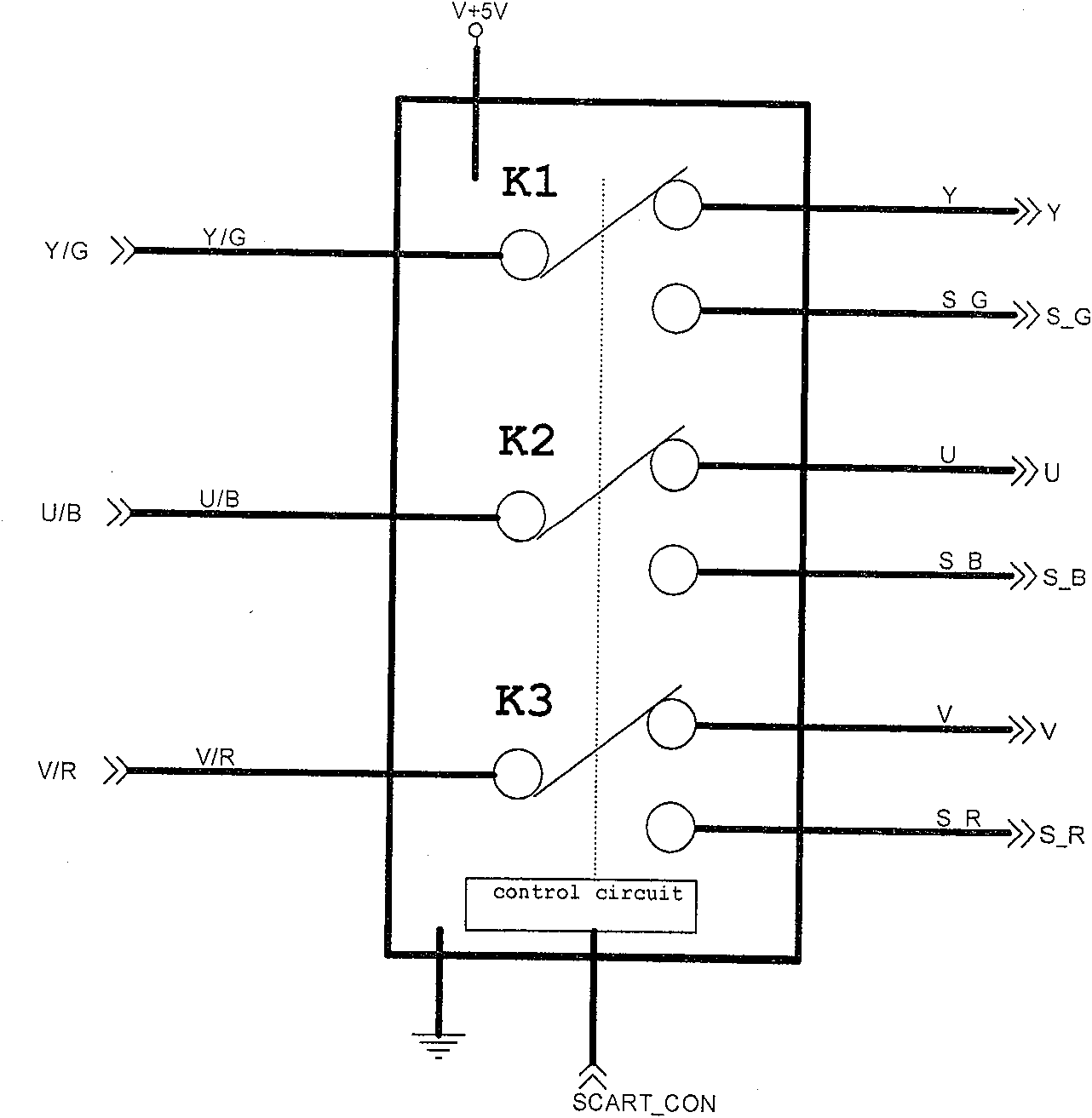
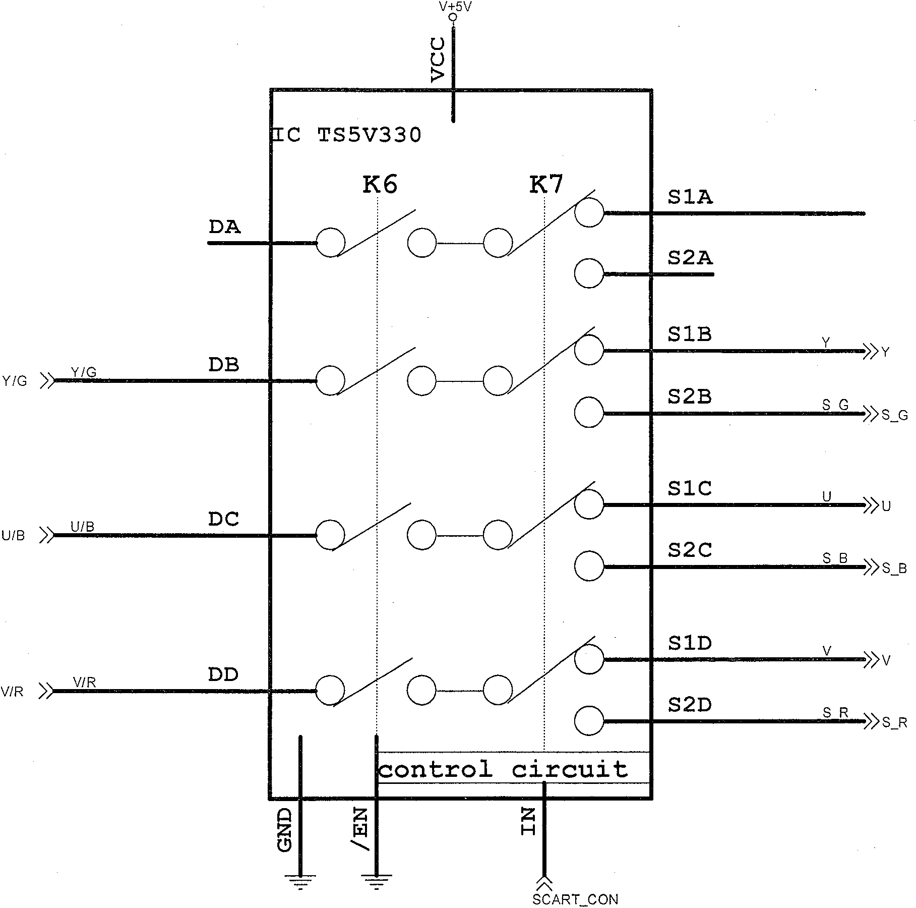
[0028] The schematic diagram of the video switching circuit provided by the embodiment of the present invention is shown in FIG. 3 , which includes a control module (control circuit) and three switch modules (K1, K2 and K3). Wherein, the input end of K1 is connected with the output end of DVD MEPG chip Y / G signal, and the two ports of the output end are respectively connected with the Y input end in the component port of the TV set and the S_G input end of the SCART port of the TV set; the input end of K2 is connected The output terminal of the DVD MEPG chip U / B signal, the two ports of the output terminal are respectively connected to the U input terminal of the TV component port and the S_B input terminal of the TV SCART port; the input terminal of K3 is connected to the DVD MEPG chip V / R signal The output terminal of the output terminal, the two ports of the output terminal are respectively connected to the V input terminal in the TV component port and the S_R input terminal...


PUM


Abstract

The invention provides a video switching circuit, comprising a control module and three switch modules (K1), (K2) and (K3); wherein, the input of the (K1) is connected with the output of the Y / G signal of the DVD decoder chip; two ports of the output are respectively connected with the Y input of the chromatic aberration variable port of the television and the S_G input of the SCART port of the television; the input of the (K2) is connected with the output of the U / B signal of the DVD decoder chip; two ports of the output are respectively connected with the U input of the chromatic aberrationvariable port of the television and the S_B input of the SCART port of the television; the input of the (K3) is connected with the output of the V / R signal of the DVD decoder chip, and two ports of the output are respectively connected with the V input of the chromatic aberration variable port of the television and the S_R input of the SCART port of the television; the control module is respectively connected with the control ports of the (K1), (K2) and (K3) to receive the SCART_CON signal, and the SCART_CON signal controls the (K1), (K2) and (K3) to choose the chromatic aberration variable port or the SCART port communicated with the television.

Description

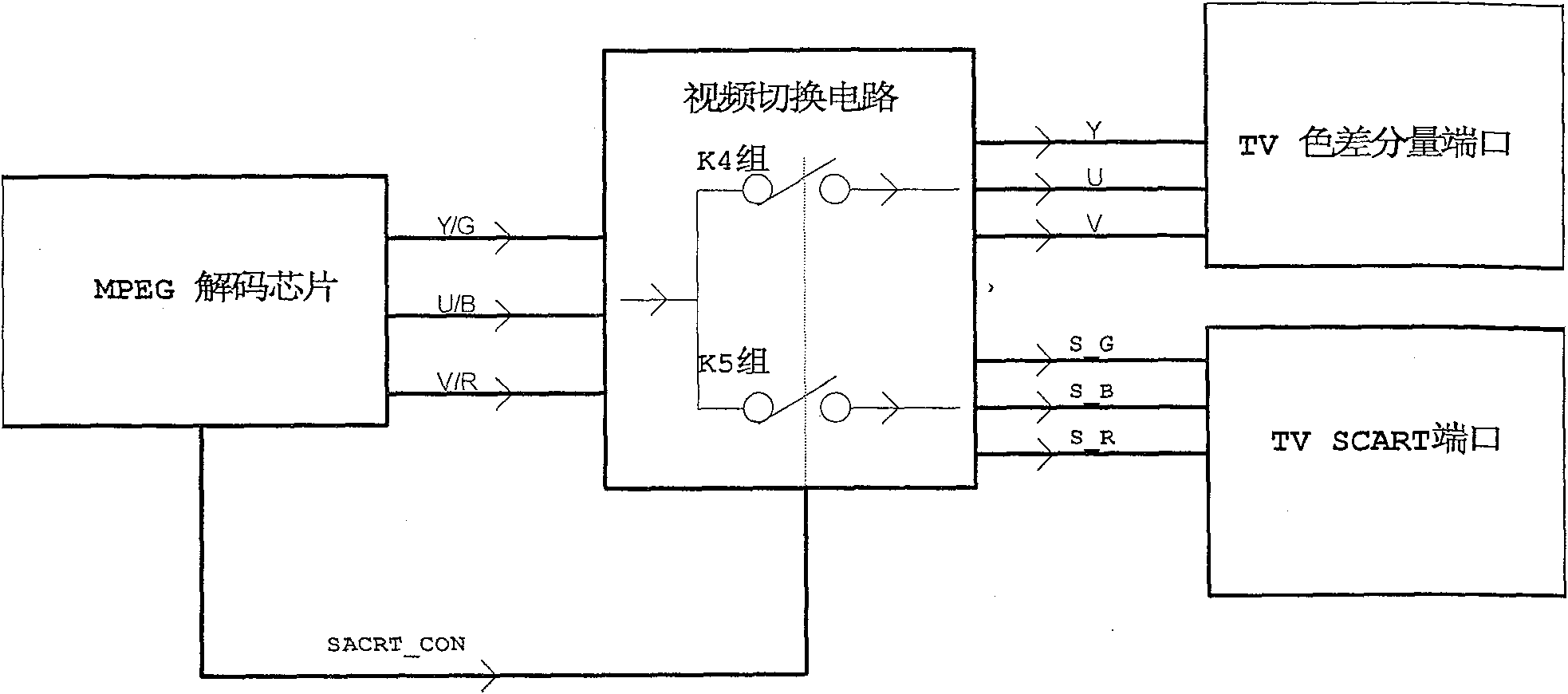
technical field [0001] The invention belongs to the field of video technology, in particular to the technology of video switching. Background technique [0002] In the DVD industry, certain certifications (such as DVD Macrovision certification) require that: when a DVD player (also including a DVD recorder) has RGB signals (SCART ports, European TV audio and video interfaces) and YUV signals (component port) video When outputting, the RGB signal cannot be output from the color difference component port, and the YUV signal cannot be output from the SCART port. [0003] However, since the YUV / RGB signals of all DVD decoding schemes share a set of video digital-to-analog conversion, that is, the RGB signals will be output from the component ports, and the YUV signals will also be output from the SCART ports. [0004] Please refer to FIG. 1 , which is a block diagram of an existing DVD with a video switching control function. This solution is to make the DVD meet the requireme...

Claims


Application Information

Patent Timeline
Patent Type & Authority Patents(China)
IPC IPC(8): H04N5/775H04N5/765
Inventor 余克球
Owner TCL TECH ELECTRONICS (HUIZHOU) CO LTD
Learn More