Automatic paint spraying machine

A technology of automatic paint spraying machine and spray booth, which is applied in the direction of spraying device, coating, and surface coating liquid device, etc., which can solve the problems of greatly increased mold cost, low degree of automation, and long cycle, so as to save mold cost, The effect of high degree of automation and high work efficiency

Inactive Publication Date: 2008-05-28
SHENZHEN KUNHAN TECH
View PDF1 Cites 44 Cited by
  • Summary
  • Abstract
  • Description
  • Claims
  • Application Information

AI Technical Summary

Problems solved by technology

However, the above-mentioned existing automatic paint spraying machine does not design any relevant sets of molds and fixed molds. It can only realize the spraying of specific areas by adjusting the position of the spraying part relative to the workpiece. It is as accurate as fixed-point spraying; although some manufacturers achieve spraying in specific areas by manually putting the mold on the workpiece before sending the workpiece into the automatic spraying machine, but because the cleaning of the spraying mold is currently carried out in an independent mold washing machine , remove the mold from the workpiece and send it to the mold washing machine for cleaning, and then send it back to the automatic paint spraying machine for use. The same mold, on the one hand, leads to the need to open multiple sets of the same mold, the cost of the mold is greatly increased, and the transportation of the mold and the mold is mainly manual operation, with a low degree of automation
It can be seen that the existing automatic paint spraying machine cannot meet the production needs of precise spray painting for specific areas

Method used


Image

  • Automatic paint spraying machine
  • Automatic paint spraying machine
  • Automatic paint spraying machine

Examples


Embodiment Construction

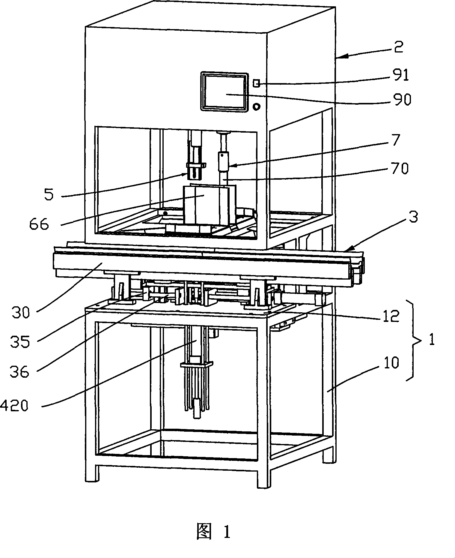
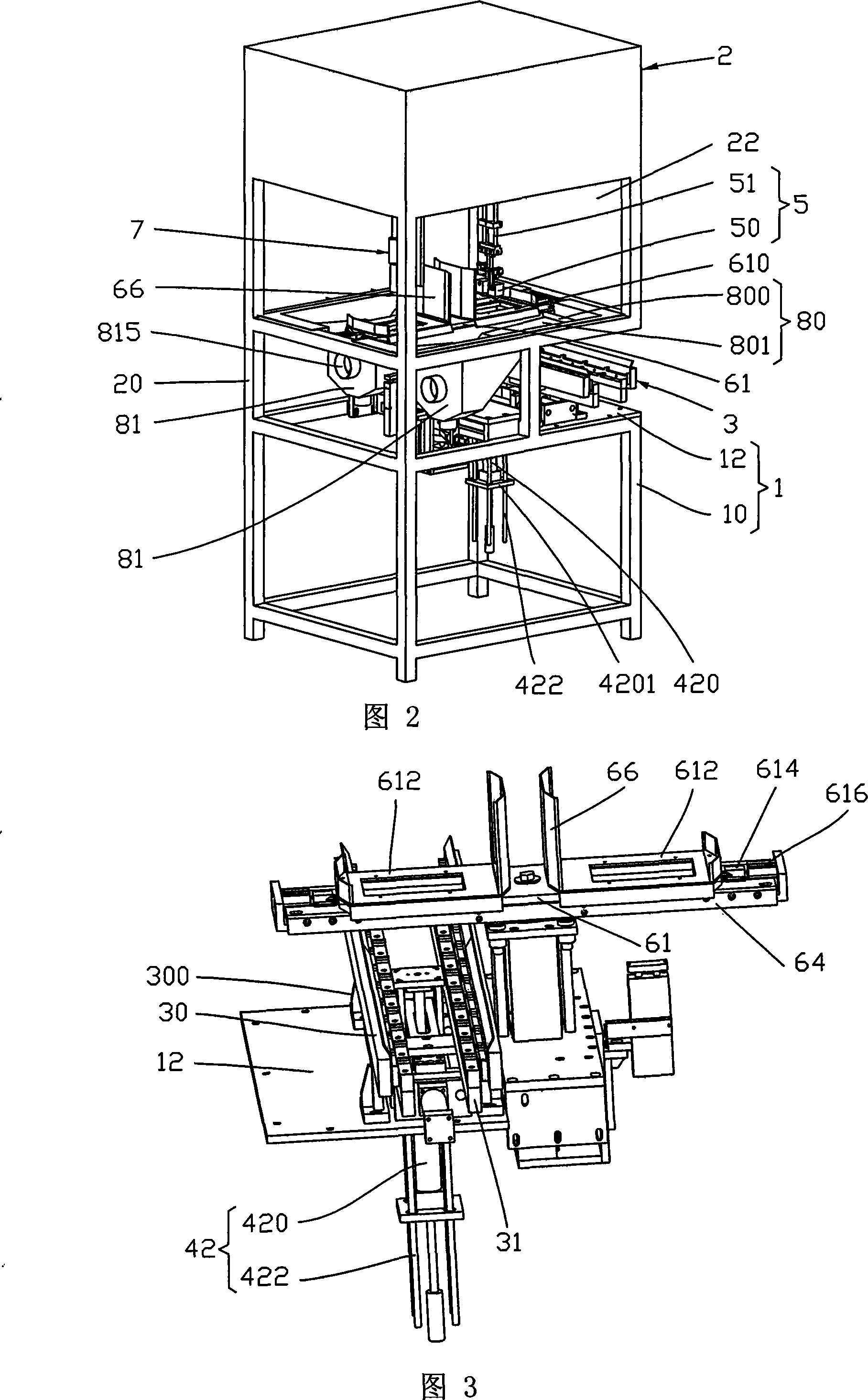
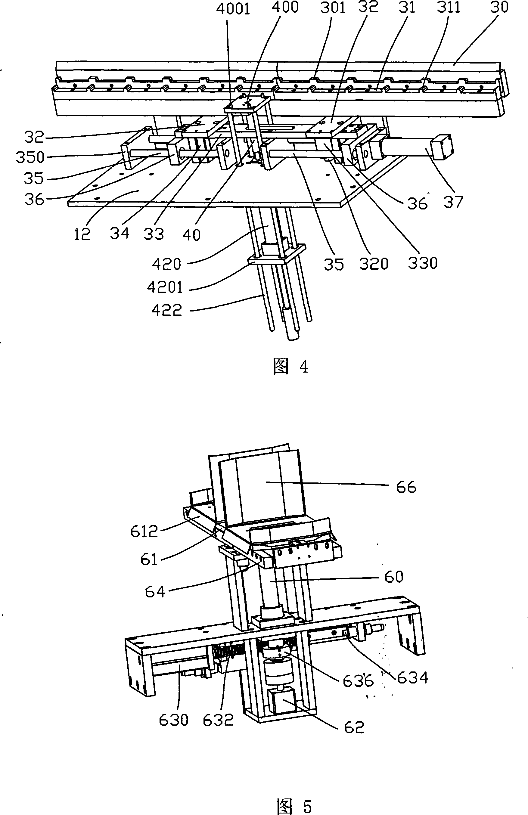
[0015] As shown in Figures 1 to 2, the present invention provides an automatic painting machine, including a machine platform 1, a paint spray booth 2 arranged above the machine platform 1, and a workpiece conveying device located on the machine platform 1 and below the paint spray booth 2 3. Mold setting device 4, paint spraying device 5, mold rotating device 6 provided with mold (not shown), mold washing device 7, sewage discharge device 8 and control system (not shown).

[0016] Wherein, the machine table 1 is a platform installed as other components, and mainly consists of a frame 10 and a platen 12 arranged on the top of the frame 10 .

[0017] Described spray booth 2 utilizes support 20 to be arranged on the top of machine platform 1, and it is a closed working chamber, and its internal area is divided into spray paint area and mold washing area, and described spray paint device 5 and mold wash device 7 are respectively located in spray paint. area and mold washing area....


PUM


Abstract

The invention relates to an automatic spray-painting machine, comprising a machine station, a spraying chamber, a work piece delivery device, a cover die device, a spraying device arranged in the spraying chamber, a rotating die device, a washing die device, a cleaning dirty device and a control system. The work piece delivery device is provided with a work piece loading plate; the cover die device comprises a cover die driving mechanism and an incremental launching column which can support the work piece loading plate and correspondingly lift and drop; the rotating die device comprises an upright column, a die base fixed on the top of the upright column, power elements for die base lifting and a rotating die driving mechanism. The die base is arranged in the spraying chamber and two ends of the die base are respectively positioned below the praying device and the washing die device. Two ends of the die base are respectively provided with dies and the middle part of the die base is provided with an isolation board. The invention can cover die automatically and do spraying and die washing work simultaneously. Only by rotating the die base, the position of the used die and the position of washed die can be exchanged, so as to realize high-speed and continual spraying process. The invention is high in automation degree and low in die cost. Due to the timely non-feculence treatment to the waste water and waster gas, the invention is also beneficial to environmental protection.

Description

technical field [0001] The invention relates to the field of painting equipment, in particular to an automatic painting machine. Background technique [0002] With the development of automation technology, more and more automatic paint spraying machines have been applied. For example, an automatic paint spraying machine disclosed in Chinese Utility Model No. ZL 02237354.3 is mainly provided with a paint spraying machine body, which includes a body and a transmission body driven by the power source of the body, wherein: the transmission body is connected to There is a transmission belt, the structure of which is driven by the transmission body to run above the body; the transmission belt is also provided with a plurality of fixing parts, and the fixing parts are respectively connected and fixed with worktables for placing workpieces. The belt connection drives the worktable to run above the body; the body is provided with more than one set of reciprocating structures with pa...

Claims


Application Information

Patent Timeline
Patent Type & Authority Applications(China)
IPC IPC(8): B05C5/00B05C13/00B05C15/00B05C21/00B05B15/04B05B15/12
Inventor 庄锦东施华斌
Owner SHENZHEN KUNHAN TECH
Why Eureka
Try Eureka