Cylindrical roller bearing

A technology of cylindrical roller bearings and cylindrical rollers, which is applied to bearing components, shafts and bearings, mechanical equipment, etc., and can solve problems such as bearing temperature rise

Active Publication Date: 2008-05-28
NTN CORP
View PDF1 Cites 2 Cited by
  • Summary
  • Abstract
  • Description
  • Claims
  • Application Information

AI Technical Summary

Problems solved by technology

[0011] However, while cylindrical roller bearings designed in this conventional manner exhibit sufficient capacity at low and high rotational speeds, there is a risk of an excessive increase in bearing temperature due to elastic deformation of the columns 14b of the cage 14
In addition, even when the method disclosed in Patent Re

Method used


Image

  • Cylindrical roller bearing
  • Cylindrical roller bearing
  • Cylindrical roller bearing

Examples


Embodiment Construction

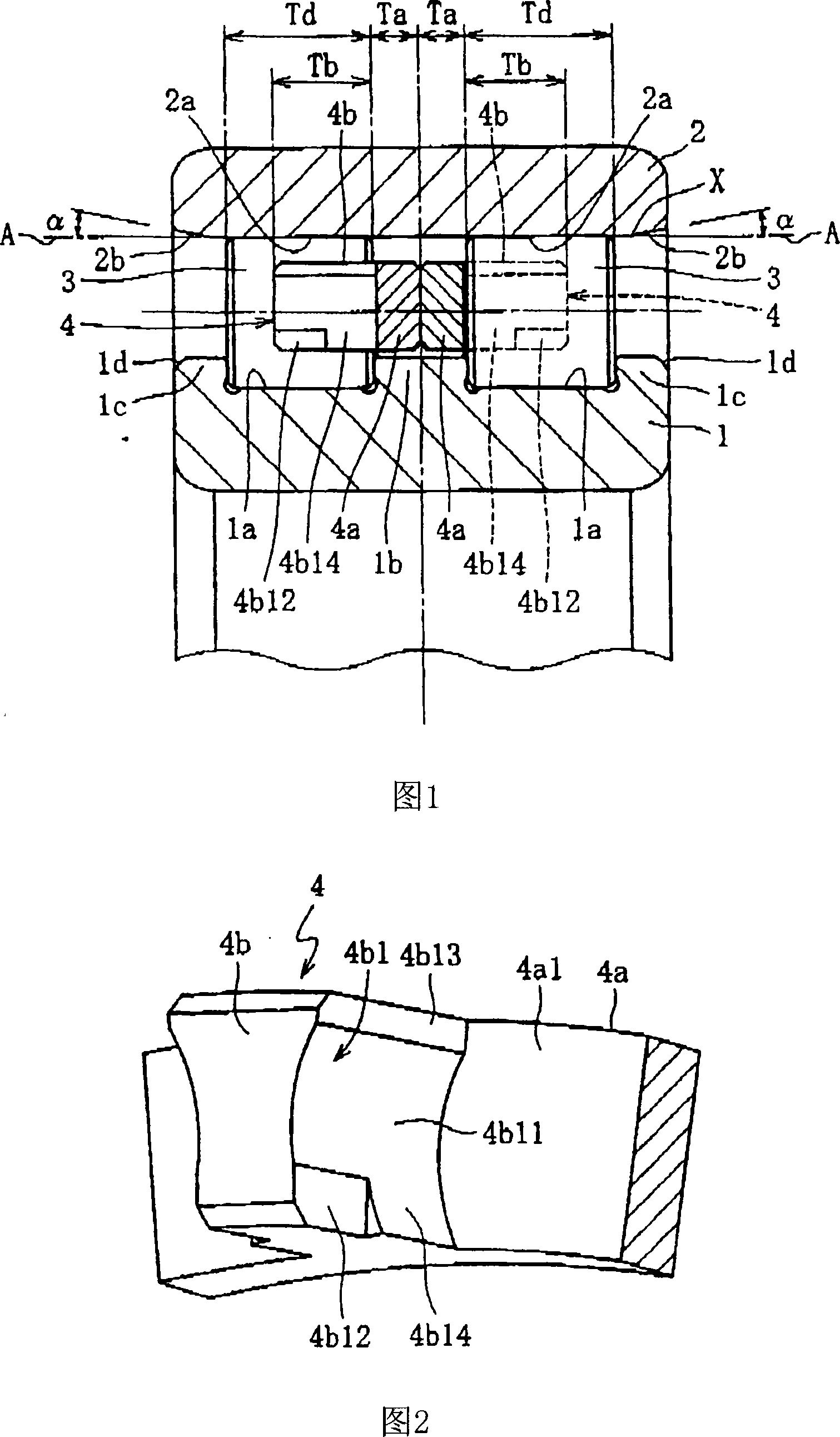
[0070] Embodiments of the present invention will be described below with reference to the drawings.

[0071] Fig. 1 shows a double row roller bearing of a first embodiment. In the main shaft device of the machine tool, such a double row roller bearing is a device for supporting the main shaft, which is rotationally driven at high speed in a freely rotatable manner with respect to the machine body. The roller bearing includes an inner ring 1 having a double-row rolling surface 1a, an outer ring 2 having a double-row raceway surface 2a, and a raceway surface 1a of the inner ring 1 and a raceway surface of the outer ring 2 provided in a free-rolling manner 2a between cylindrical rollers 3, and a pair of cages 4 made of synthetic resin supporting each cylindrical roller 3. A central flange 1b is located at the center of the inner ring 1 in the axial direction, and outer flanges 1c are located at both ends.

[0072] Undercut portions 2b are formed at both axially outer ends of th...


PUM


Abstract

A cage for a cylindrical roller bearing includes an annular portion, a plurality of posts extending in a unitary, continuous manner from the inner surface of the annular portion, and a plurality of pockets forming a gap between the inner circumferential sides of adjacent posts. Space, and the cylindrical roller is supported in a free-rotating manner. The axial side of the column includes arcuate surfaces formed in the ID and OD directions from the pocket PCD (pitch circle) that passes through the pocket center of the pocket, and a rolling pin at the inner peripheral portion of the tip. Go to the part (lubrication groove).

Description

[0001] This application is a divisional application with an application date of September 29, 2004, an application number of 200410080624.5, and an invention name of "cylindrical roller bearing". technical field [0002] The present invention relates to a cylindrical roller bearing including a cage made of synthetic resin, and more particularly to a cylindrical roller bearing for supporting a spindle rotating at high speed, such as a machine tool. Background technique [0003] It is well known that in machine tools, such as machining centers, numerically controlled lathes and presses, the main shaft is usually supported by bearings which rotate freely relative to the machine body. The orientation of the spindle is divided into two main categories according to the type of machine, vertical (where the axis is arranged along a vertical direction) and horizontal (where the axis is arranged along a horizontal direction). In addition, oil lubrication such as grease lubrication, ai...

Claims


Application Information

Patent Timeline
IPC IPC(8): F16C33/49F16C33/66
Inventor 山本直太水谷守
Owner NTN CORP
Why Eureka
Try Eureka