Cart-Type Transporting Device

Inactive Publication Date: 2017-09-07
DAIFUKU CO LTD
View PDF0 Cites 0 Cited by
  • Summary
  • Abstract
  • Description
  • Claims
  • Application Information

AI Technical Summary

Benefits of technology

The present invention is a transporting device for a cart in a turning pathway section, where the cart is lifted and lowered. The invention provides a solution for preventing the cart from moving by gravity and ensuring stable support during the lifting and lowering process. The invention uses an auxiliary rotating body and an endless chain to support the cart at multiple points, allowing for smooth operation and preventing excessive strain on the cart's front-side engaged section. The invention also includes an arc-shaped guide rail and a lower protruding cam to further guide and support the cart during the turning pathway section. The invention can be easily practiced and can be used even for heavy items.

Problems solved by technology

Consequently, significant strength beyond the original necessary strength is required for those, and moreover, it is difficult to smoothly start the scooping-up operation.
Since a load on the rear half portion of the transporting cart is received by the second rear-side engaged section (such as the cam-following roller) which largely extends from the transporting cart (the loading platform) in a lateral direction, it is difficult to apply this configuration to a transporting device for transporting a heavy item.
An extremely complicated mechanism is needed in order to achieve a configuration in which the second rear-side engaged section and the second front-side engaged section are selectively made to act according to the traveling direction of the transporting cart, with the result that it is difficult to practically adopt this configuration.

Method used


Image

  • Cart-Type Transporting Device
  • Cart-Type Transporting Device
  • Cart-Type Transporting Device

Examples


Embodiment Construction

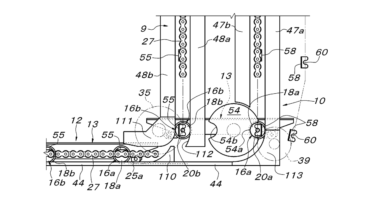
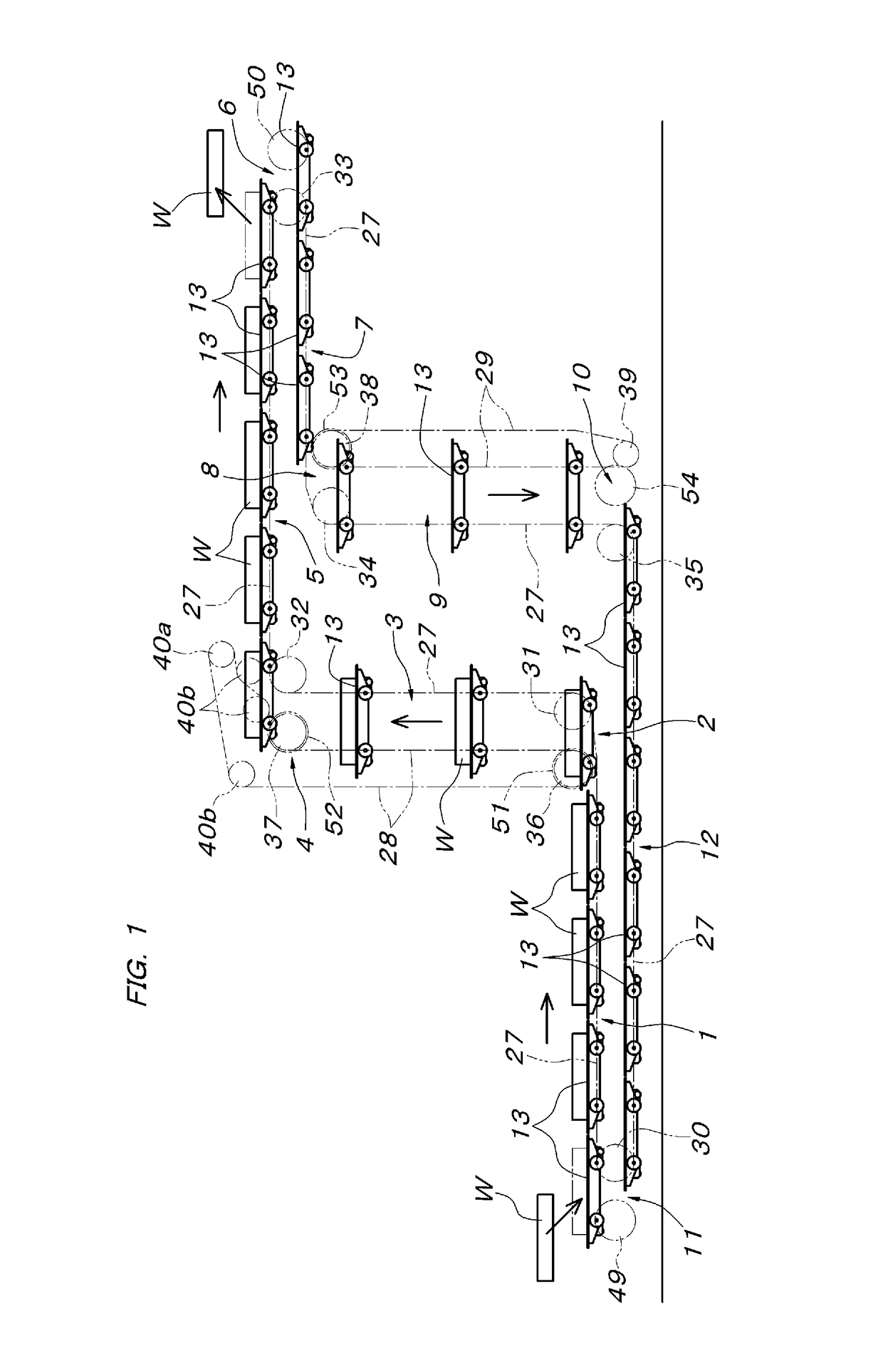
[0046]An embodiment of the present invention will be described below with reference to accompanying drawings. As shown in FIGS. 1 and 3, a transporting device of the embodiment is formed with: a low-position first horizontal pathway section 1; a first lifting / lowering pathway section 3 which is connected upward to one end of the first horizontal pathway section 1 via a first turning pathway section 2; a high-position second horizontal pathway section 5 which is arranged on the opposite side to the side where the first horizontal pathway section 1 is present with respect to the first lifting / lowering pathway section 3 and which is connected to the upper end of the first lifting / lowering pathway section 3 via a second turning pathway section 4; a third horizontal pathway section 7 which overlaps the lower side of the second horizontal pathway section 5 and which is connected to the free end of the second horizontal pathway section 5 via a third turning pathway section 6; a second lift...


PUM


Abstract

A cart-type transporting device includes left and right auxiliary rotating bodies moving in conjunction with left and right turning-section toothed wheels that guide a first endless chain; and a turning pathway section that protrudes at a position between the auxiliary rotating bodies, and that is provided with a lower protruding cam over which a transporting cart can pass. Left and right front-side projection shafts of the transporting cart engage with an engagement section of the respective auxiliary rotating bodies. Left and right rear-side projection shafts engage with an engagement section of the first endless chain. When the projection shafts are picked up by the rotation of the turning-section toothed wheels and the auxiliary rotating bodies, the lower protruding cam supports and guides a cam-following roller at a bottom section of the transporting cart in accordance with the same rotating pathway as the engagement section.

Description

FIELD OF THE INVENTION[0001]The present invention relates to a cart-type transporting device in which a transporting cart travels on a given traveling pathway while constantly keeping a horizontal upright posture.BACKGROUND OF THE INVENTION[0002]Various types of cart-type transporting devices have been known in which a traveling pathway that includes a turning pathway section in a vertical direction between a horizontal pathway section and a separate traveling pathway section connected thereto, a transporting cart that travels the traveling pathway while keeping a horizontal upright posture and a drive means that makes the transporting cart travel in the traveling pathway are provided. For example, in a cart-type transporting device disclosed in Japanese Published Unexamined Patent Application No. H6-171718 (Patent Literature 1), wheels which are pivotally supported to both left and right sides of a transporting cart and which are provided so as to protrude are used as engaged secti...

Claims


Application Information

Patent Timeline
IPC IPC(8): B65G17/12B65G1/127B65G17/14
CPCB65G17/123B65G17/14B65G1/127B65G1/02B65G1/04B65G17/48B65G17/12B65G17/30B65G17/38B65G17/42B65G1/12B65G35/06B65G17/26B65G2812/017
Inventor ISHIBASHI, MASAHIROMURANAGA, JUNICHIBABA, SHIGERUTAMURA, YUKICHIKUSUHARA, SHIGEYUKI
Owner DAIFUKU CO LTD
Why Eureka
Try Eureka