Toner transport mechanism and image forming apparatus

Active Publication Date: 2018-10-11
CANON KK
View PDF0 Cites 1 Cited by
  • Summary
  • Abstract
  • Description
  • Claims
  • Application Information

AI Technical Summary

Benefits of technology

The present invention provides a technique to detect and prevent abnormal and incorrect detection of a toner transport mechanism with a simple configuration. This helps to improve the efficiency and accuracy of the toner transport mechanism.

Problems solved by technology

However, an apparatus configuration described in Japanese Patent Application Laid-open No. 2017-21123 represents a configuration which uses a large space inside the recovery container of unnecessary toner, and spatial constraints may arise when the apparatus configuration is to be provided at other locations.
For example, when the same configuration is applied on the toner transport path with a smaller space than the recovery container, the configuration may inhibit the transportation of toner and may cause clogging.
Furthermore, since there is a risk that penetration of toner into a detection sensor portion may cause erroneous detection, a component for sealing a space between the toner transport path and the detection sensor is generally provided.
However, with the configuration described in Japanese Patent Application Laid-open No. 2017-21123, since a connecting portion between the flag member and the detection sensor is located in a toner transport region by the transporting member, there is a risk that toner may leak from the connecting portion and adhere to a detecting portion to impair detection accuracy.

Method used


Image

  • Toner transport mechanism and image forming apparatus
  • Toner transport mechanism and image forming apparatus
  • Toner transport mechanism and image forming apparatus

Examples


first embodiment

[0040]Hereinafter, a toner transport mechanism and an image forming apparatus provided with the toner transport mechanism according to an embodiment of the present invention will be described with reference to the drawings. Examples of image forming apparatuses to which the present invention is applicable include image forming apparatuses such as copiers, printers, and facsimiles which form an image on recording material using an electrophotographic system. In addition, while a transportation object of the toner transport mechanism is mainly untransferred residual toner (toner remaining on an image bearing member without being transferred to recording material or an intermediate transfer member or toner remaining on the intermediate transfer member without being secondarily transferred to recording material), transportation objects also include residual objects other than toner such as a scrap of paper and dust.

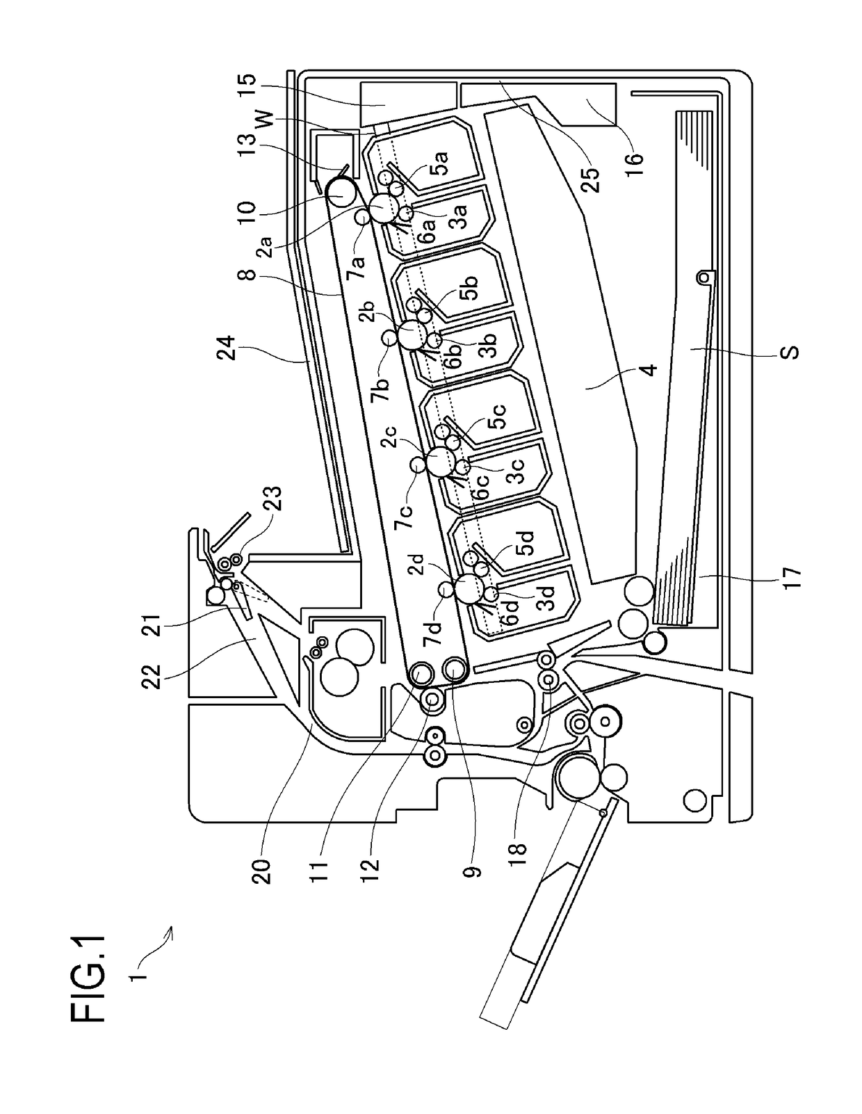
[0041]FIG. 1 is a schematic sectional view showing a configuration of a ...

second embodiment

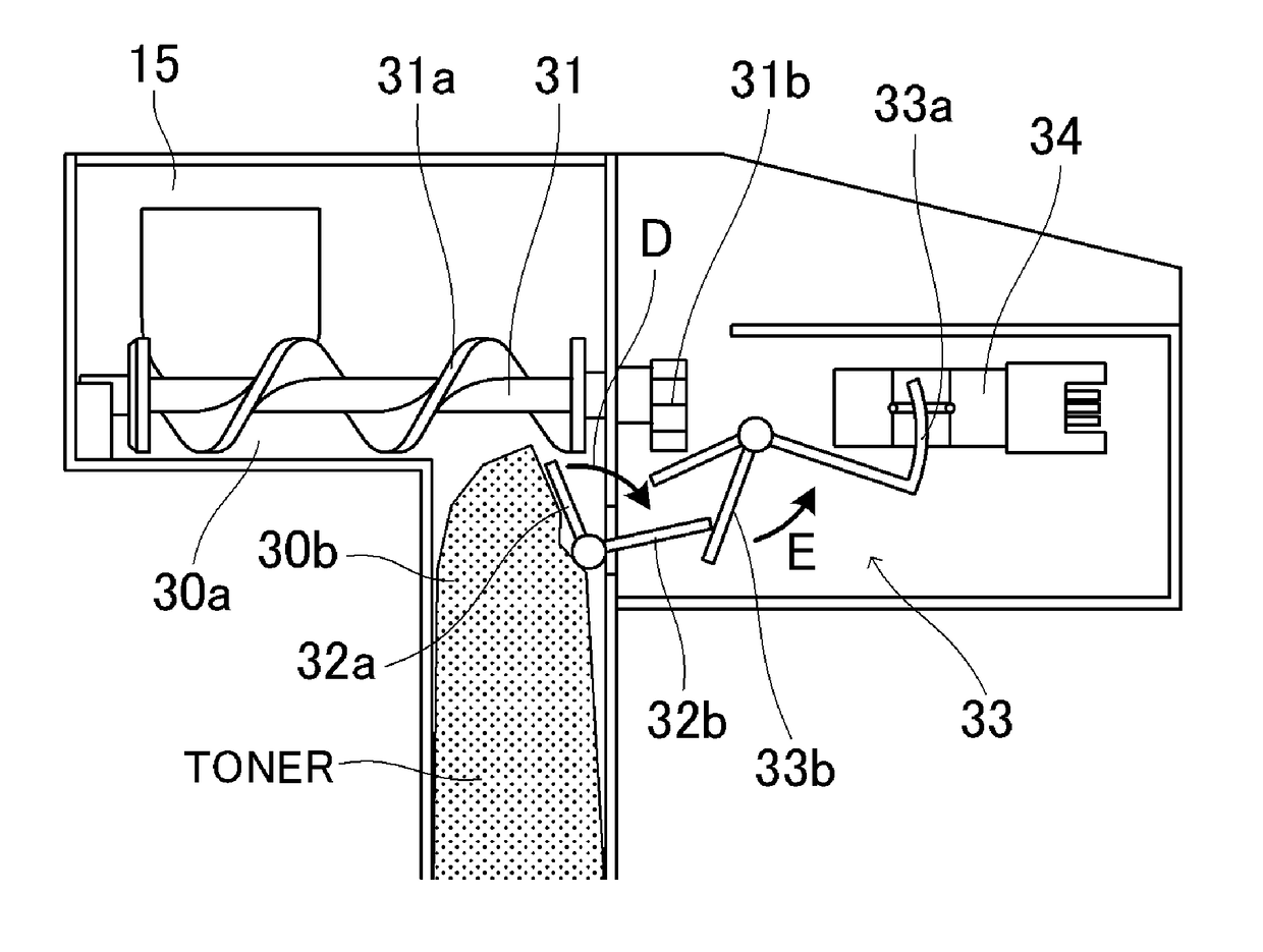
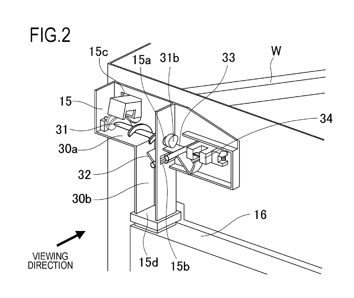
[0065]A toner transport mechanism and an image forming apparatus according to a second embodiment of the present invention will be described with reference to FIG. 6 and FIGS. 7A and 7B. In a configuration of the image forming apparatus according to the second embodiment, since components other than the toner delivery duct in the toner transport path are the same as those in the first embodiment, a description thereof will be omitted. In the components of the toner delivery duct according to the second embodiment, characteristic portions that differ from the first embodiment will be mainly described.

[0066]FIG. 6 is a schematic perspective sectional view capturing an overall picture of the toner transport mechanism according to the second embodiment of the present invention, of which an internal structure has been made easily visible by removing a wall portion of the toner delivery duct 15, an outer wall cover of the apparatus main body, and the like on a near side (a side opposite t...


PUM


Abstract

Provided is a toner transport mechanism including: a first movable member which is displaced in accordance with an amount of toner in a transport path for transporting toner; a second movable member which is displaced in accordance with a rotation of a transporting member provided in the transport path; and a flag member which is displaced to an acting position where the flag member acts on a sensor and a non-acting position where the flag member does not act on the sensor, in accordance with the displacement of the first movable member and the displacement of the second movable member, the sensor being arranged outside of a duct and detecting an anomaly of the toner transport mechanism.

Description

BACKGROUND OF THE INVENTIONField of the Invention[0001]The present invention relates to a toner transport mechanism used in an electrophotographic image forming apparatus.Description of the Related Art[0002]Image forming apparatuses, such as copiers, printers and facsimiles, which form an image on recording material using an electrophotographic system may adopt a configuration in which toner such as untransferred toner having been generated in an image forming process and having become unnecessary without being transferred onto the recording material is transported to and stored in a recovery container. While transportation of unnecessary toner generally involves rotating a transporting member such as a screw or a spring installed on a transport path to transport the unnecessary toner to the recovery container, toner leakage sometimes occur due to damage, an assembly error, or the like of the transporting member preventing the toner from being normally transported. Therefore, it is ...

Claims


Application Information

Patent Timeline
IPC IPC(8): G03G21/00
CPCG03G15/55G03G15/095G03G21/105G03G15/0879G03G21/12
Inventor SUZUKI, YOSHIMI
Owner CANON KK
Why Eureka
Try Eureka