Thermal printer and thermal printing method

Inactive Publication Date: 2006-03-30
FUJIFILM CORP +1
View PDF3 Cites 2 Cited by
  • Summary
  • Abstract
  • Description
  • Claims
  • Application Information

AI Technical Summary

Benefits of technology

[0008] In view of the foregoing, it is an object of the present invention to provide a thermal printer and a thermal printing method for preventing occurrence of uneven density due to transport load fluctuation of a recording sheet.
[0012] According to the present invention, since the total printing heat energy in each line is kept constant by providing unrecording area at one side or both sides of the recording sheet and by driving heating elements corresponding to both the recording area and the unrecording area with the heating elements corresponding to the recording area, the transport load fluctuation of the recording sheet is prevented. Therefore, it is possible to the control the transport load fluctuation with a simple structure and to prevent occurrence of uneven density and uneven color due to the transport load fluctuation.

Problems solved by technology

When the printing heat energy is large, the friction coefficient becomes small due to an increase of temperature of the heating elements.
When the printing heat energy is small, the friction coefficient becomes large due to a decrease of temperature of the heating elements.
There is a problem that the printing heat energy applied to each unit area changes to cause uneven density.
Thereby, a problem arises in that it is necessary to obtain various data by actually operating each printer, thereby time and labor is required for obtaining data.
Moreover, there is a problem that it is impossible to correct the printing heat energy sufficiently even when the printing heat energy is corrected by using the obtained data, since the transport load fluctuation is suppressed by correction of the printing heat energy, not by directly acting on the recording sheet.

Method used


Image

  • Thermal printer and thermal printing method
  • Thermal printer and thermal printing method
  • Thermal printer and thermal printing method

Examples


Embodiment Construction

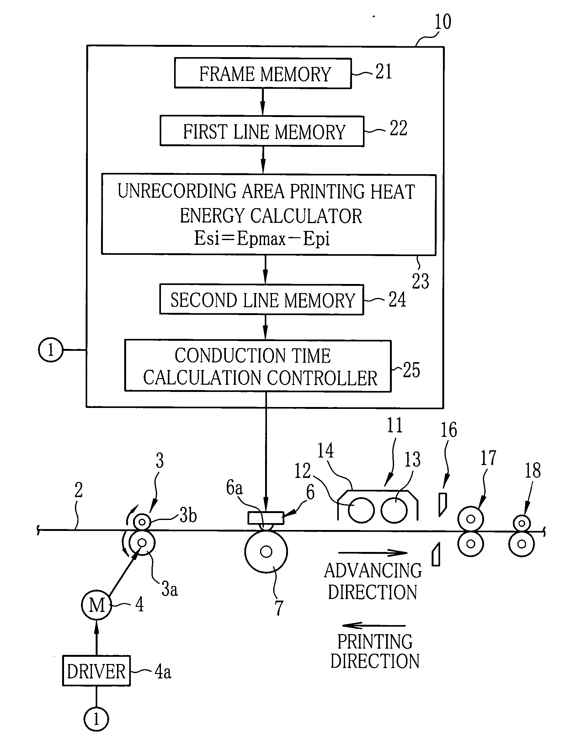
[0018] In FIG. 1, a color direct thermal printer prints an image on a continuous color thermosensitive recording sheet (hereinafter referred to as recording sheet) 2 supplied from a roll (not shown). The recording sheet 2 is transported by a transporting roller pair 3 both in an advancing direction and in a printing direction opposite to the advancing direction. A transporting roller pair 3 includes a capstan roller 3a driven by a transport motor 4 and a pinch roller 3b movable between the pressing position to the capstan roller 3a and the retracted position therefrom. A pulse motor is used for the transport motor 4 and is controlled by a controller 10 through a driver 4a.

[0019] It is known that the recording sheet 2 includes a cyan thermosensitive coloring layer, a magenta thermosensitive coloring layer and a yellow thermosensitive coloring layer, and a protective layer overlaid on a support in sequence. The yellow thermosensitive coloring layer, a topmost layer is most sensitive ...


PUM


Abstract

The recording sheet is virtually divided into a recording area and an unrecording area in a main scan direction. Unrecording area printing heat energy is Esi calculated by subtracting printing heat energy Epi for a line to be printed from maximum printing heat energy Epmax for printing each line in the recording area. Common printing heat energy is calculated by dividing the unrecording area printing heat energy Esi by the number of the heating elements in the unrecording area. Virtual image data for each heating element is obtained by counting backward from the common printing heat energy. A recording sheet is printed based on the virtual image data and the real image data. Total printing heat energy is kept constant in each line, and there occurs no printing heat energy fluctuation on printing. Transport load fluctuation due to the printing heat energy fluctuation is suppressed to prevent an uneven density.

Description

BACKGROUND OF THE INVENTION [0001] 1. Field of the Invention [0002] The present invention relates to a thermal printer and a thermal printing method for thermally recording an image on a recording sheet with a thermal head. [0003] 2. Background Arts [0004] A direct thermal printer including a thermal head which thermally records an image by coloring onto a thermosensitive recording sheet provided with thermosensitive coloring layers, is known. A plurality of heating elements is aligned on the thermal head in a main scan direction. The direct thermal printer records the image on the recording sheet line by line while relatively moving the thermal head and the recording sheet in a sub scan direction. Each heating element is driven based on image data of one line to apply printing heat energy to the recording sheet. [0005] Friction coefficient between the recording sheet and the thermal head fluctuates according to the printing heat energy. When the printing heat energy is large, the f...

Claims


Application Information

Patent Timeline
IPC IPC(8): B41J2/32
CPCB41J2/36
Inventor CUI, SHENGFU
Owner FUJIFILM CORP
Why Eureka
Try Eureka