
Power cell source test method

A power battery and battery technology, applied in the direction of measuring electricity, measuring devices, measuring electrical variables, etc., can solve the problems of failure to alarm in time, failure to work, damage, real-time monitoring and management, etc., to achieve rapid measurement and real-time monitoring, and easy to promote Application, life extension effect

Inactive Publication Date: 2008-05-28
HARBIN INST OF TECH
View PDF1 Cites 11 Cited by
  • Summary
  • Abstract
  • Description
  • Claims
  • Application Information

AI Technical Summary

Problems solved by technology

[0003] The purpose of the present invention is to solve the problems of large errors in the measurement and calculation of the working voltage, current and temperature of the power battery and the measurement and calculation of the energy SOC of the battery in the prior art, the measurement reflection speed is slow, the alarm cannot be prompted in time, and the Real-time monitoring and management of the working process, resulting in damage to a single battery due to overvoltage or undervoltage

Method used


Image

  • Power cell source test method

Examples


specific Embodiment approach 1

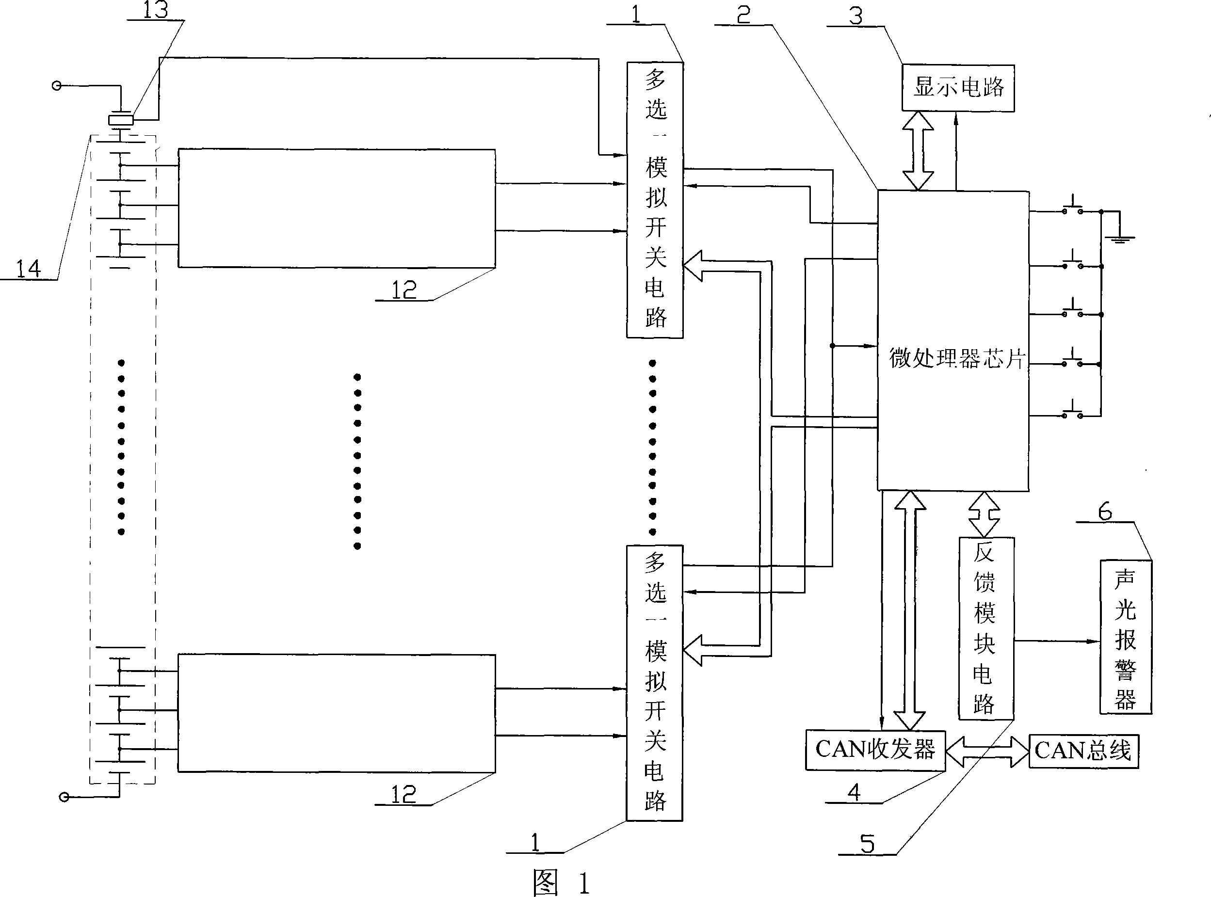
[0010] Specific embodiment one: illustrate this embodiment in conjunction with Fig. 1, the method step of this specific embodiment is:

[0011] Step 1: Initialize microprocessor chip 2, display circuit 3, multi-select one analog switch circuit 1, CAN transceiver 4; set standard comparison voltage parameters, comparison current parameters, and comparison temperature parameters;

[0012] Step 2: The microprocessor chip 2 performs A / D conversion on the cycle voltage, current and temperature data of each battery of the battery source collected by the multi-choice analog switch circuit 1 and the voltage balance detection circuit 12, and then converts it into a numerical value , and then compared with the preset comparison voltage parameters, comparison current parameters, and comparison temperature parameters respectively. When the comparison result is not within the standard range, that is, too large or too small, an abnormal flag will be set; and all the above data will be stored ...


PUM


Abstract

The invention discloses a method for testing dynamic battery sources, which relates to the battery sources testing technique field. The invention solves existing technique problems that bigger errors are existed in tests and calculations of working voltages, electric currents of dynamic batteries, and battery energy SOC, testing and reflecting speed is low, immediate alarming hints and monitoring management for working process are not available, which leads to damages for a single battery due to battery over pressure and battery under pressure. The method comprises initializing a system, setting standards to compare with electric parameters, comparing the electric parameters, comparing temperature parameters, waiting for interrupting orders, comparing, marking, and storing collected periodic electric voltages, the electric currents, temperature data of each battery of the battery sources, executing alarming operations according to marking data. The invention can test precisely and rapidly the working voltages, the electric currents, temperature, and battery energy SOC of the dynamic batteries. The invention can avoid battery over discharging and battery overcharge and can send sound and light alarm hints.

Description

technical field [0001] The invention relates to the technical field of measurement of power battery sources. Background technique [0002] The power battery source refers to a battery pack that can provide powerful power. It is suitable for applications requiring high-energy battery power, such as hybrid vehicles, electric vehicles, portable radios, and mobile data base stations. The power battery pack is generally composed of multiple batteries connected in series. After multiple batteries are connected in series, there will be unbalanced charging and discharging of each battery during use. The specific performance is that some batteries are overcharged or overdischarged. If not controlled, some batteries will be damaged and affect the performance and life of the entire battery pack. For example, the energy SOC (State of Charge, referred to as SOC, that is, the battery power) of the battery will be lower than that of other batteries. If the discharge continues, the voltag...

Claims


Application Information

Patent Timeline
IPC IPC(8): G01R31/36
Inventor 崔刚刘宏伟左德承吴智博杨孝宗董剑舒燕君苗百利付忠传姜远致向琳张展罗丹彦王玲温东新阙子杨
Owner HARBIN INST OF TECH
Learn More