Molding condition setting method

A technology of condition setting and mold clamping force, which is applied in chemical instruments and methods, transportation and packaging, plastic recycling, etc., can solve the problems of applying mold clamping force, and achieve the control of mold clamping force and high precision mold clamping force The effect of the control

Inactive Publication Date: 2008-05-28
SUMITOMO HEAVY IND LTD
View PDF3 Cites 8 Cited by
  • Summary
  • Abstract
  • Description
  • Claims
  • Application Information

AI Technical Summary

Problems solved by technology

Therefore, there is a problem that the mold clamping force cannot be applied with high precision by operating the toggle mechanism further forward from the position where the toggle support of the main body should be stopped.

Method used


Image

  • Molding condition setting method
  • Molding condition setting method
  • Molding condition setting method

Examples


Embodiment Construction

[0040] One embodiment of the present invention will be described with reference to the drawings.

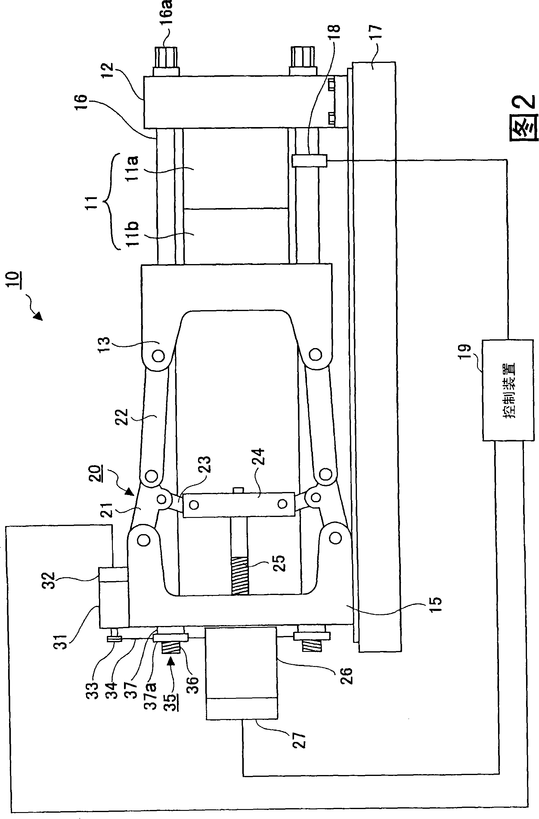
[0041] Fig. 2 is a side view of a mold clamping device of a molding machine for implementing a molding condition setting method according to an embodiment of the present invention. In Fig. 2, the clamping device 10 of the injection molding machine has: a frame body 17; a fixed plate 12 as a fixed mold supporting device fixed on the frame body 17; The substrate is provided so as to move relative to the frame body 17 at a predetermined distance. The toggle support 15 functions as a toggle type mold clamping device support device. Between the fixed plate 12 and the toggle support 15 a plurality of (for example four) connecting rods 16 as guide units extend.

[0042] The movable plate 13 is provided facing the fixed plate 12, and functions as a movable mold supporting device provided so as to be able to move forward and backward (movable in the left-right direction in the figure) a...


PUM


Abstract

A molding condition setting method capable of accurately stopping a toggle support at a specified position by accurately determining whether mold touch is performed or not in a mold thickness adjusting method. The toggle support (15) is retreated to a position where the mold touch is absent, a movable platen (13) is moved to a mold fully closed position, a mold is opened by such a distance that a prescribed mold clamping force is applied to the mold, the toggle support is advanced in a mold closing direction, and detected values from a mold clamping force sensor are monitored. When the detected values reach a threshold, the toggle support is stopped. The mold clamping force sensor comprises a tie-bar strain sensor (18) detecting the strain of a tie-bar and a pressure sensor (40) detecting a pressing force applied to the movable platen (13A) or a strain sensor (41) detecting the strain of the component of a toggle mechanism.

Description

technical field [0001] The present invention relates to a molding condition setting method, in particular to a molding condition setting method in a mold clamping device using a toggle mechanism. Background technique [0002] The mold device is generally composed of a fixed mold and a movable mold. The movable mold advances and retreats relative to the fixed mold through the mold clamping device to perform mold closing, mold clamping and mold opening. The mold clamping device has a fixed plate on which a fixed mold is attached, a movable plate on which a movable mold is attached, and a toggle mechanism as a movement mechanism for advancing and retreating the movable plate. That is, the toggle structure is driven to move the movable plate in the direction of approaching or separating from the fixed plate, thereby performing mold closing, mold clamping, and mold opening of the mold device. (For example, refer to Patent Document 1) [0003] In the above-mentioned mold clampin...

Claims


Application Information

Patent Timeline
Patent Type & Authority Applications(China)
IPC IPC(8): B29C45/66B29C45/76
CPCB29C2945/76006B29C2945/76103B29C2945/76943B29C2945/76234B29C45/661B29C2945/7623B29C45/766B29C2945/76391B29C45/1751B29C45/7653B29C2945/76227B29C2945/76013B29B17/00B29C33/505B29K2021/00C08J11/16C08J11/18C08J2321/00Y02W30/62B09B3/40B29C45/66B29C45/76
Inventor 小林彰久伊藤晃
Owner SUMITOMO HEAVY IND LTD
Why Eureka
Try Eureka