Strain sensing system

a technology of strain sensing and sensing device, applied in the field of biomedical implants, to achieve the effect of convenient mounting method and measurement of strain amplification

Inactive Publication Date: 2006-02-16
GLOBUS MEDICAL INC
View PDF7 Cites 58 Cited by
  • Summary
  • Abstract
  • Description
  • Claims
  • Application Information

AI Technical Summary

Benefits of technology

[0006] The present invention provides a miniature sensor for measuring strain in a loaded element with a radio frequency telemetry circuit utilized to transmit data derived from the output of the sensor to a remotely located reader. The telemetry circuit and sensor may be powered via inductive coupling from the reader so that no power source is required to be placed in vivo in implantation applications. Furthermore, a bio-compatible housing may be used to encapsulate the sensor and telemetry components and provide a convenient method for mounting the system on orthopedic implant devices, as well as provide some measure of strain amplification.

Problems solved by technology

Rod strain levels that do not decrease over time, increase somewhat, or change abruptly could be indicative of implant failure.

Method used


Image

  • Strain sensing system
  • Strain sensing system
  • Strain sensing system

Examples


Embodiment Construction

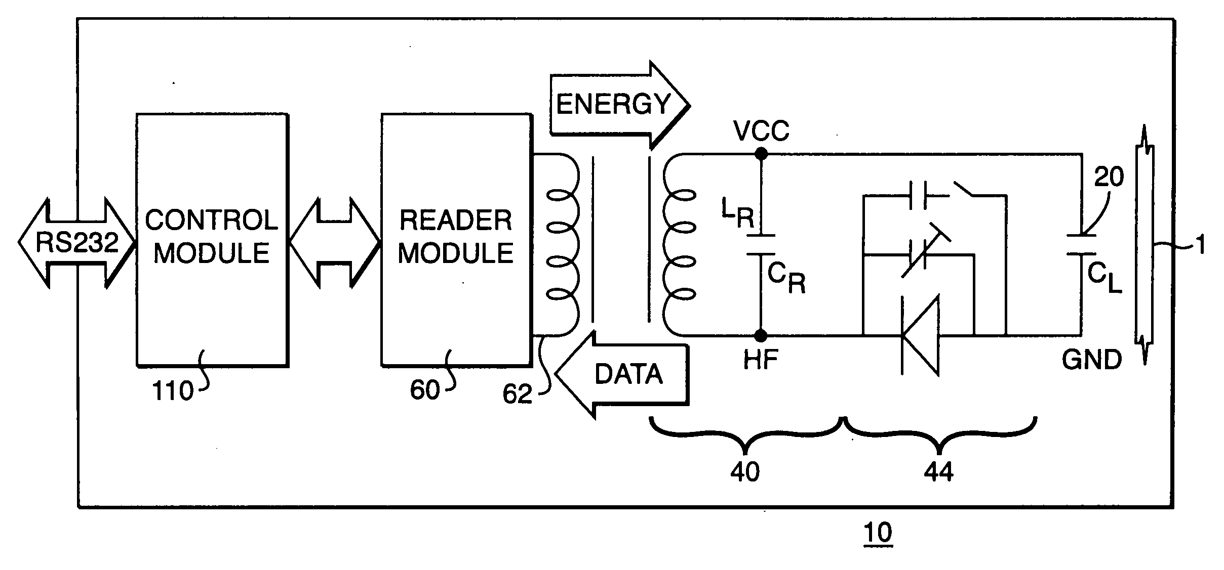
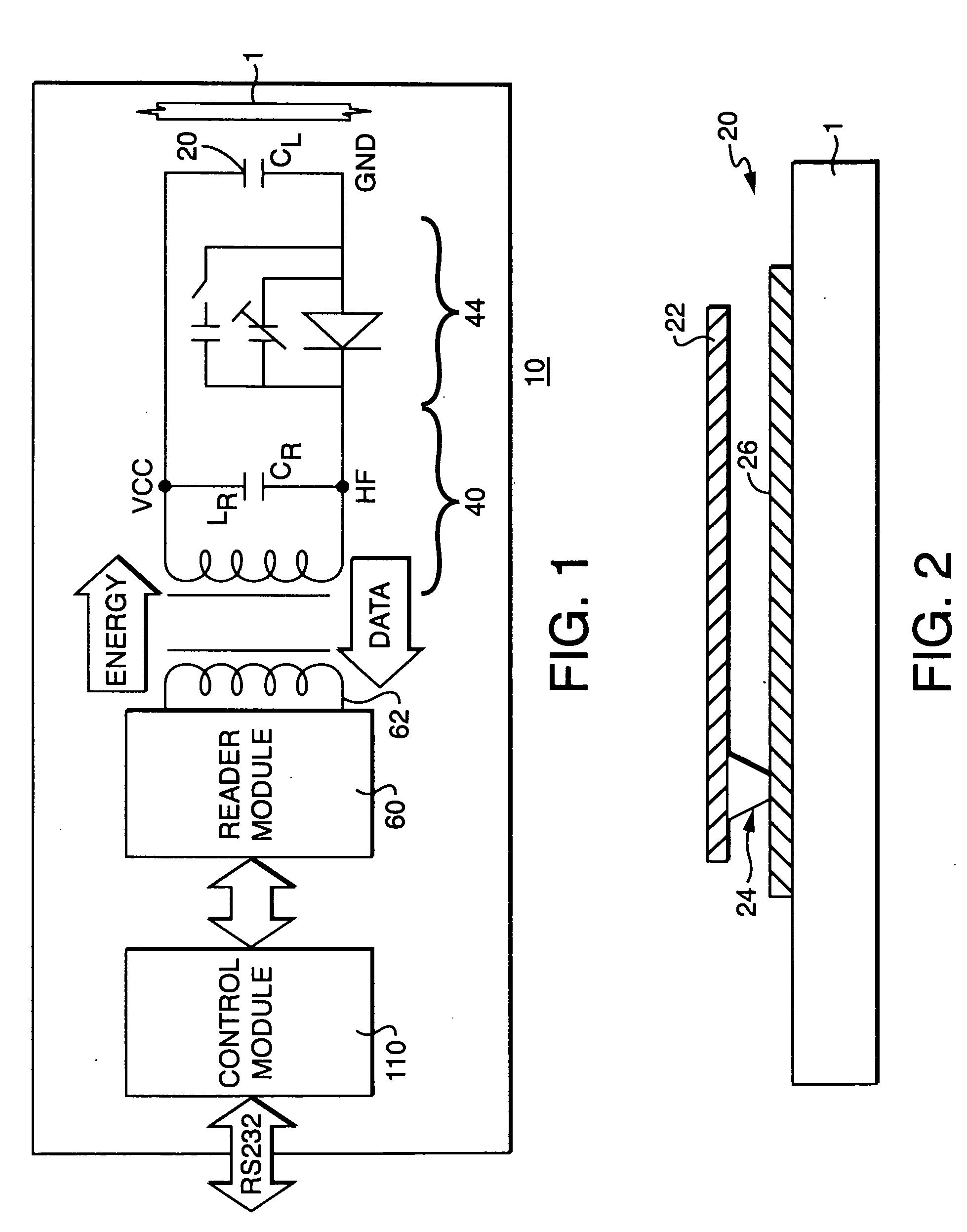
[0026] Referring to FIG. 1 and in accordance with one embodiment of the instant invention, a system 10 for measuring and remotely monitoring strain in an element 1 subject thereto includes a sensor 20 capable of measuring static and dynamic strain in the element 1, a telemetry circuit 40 that transmits sensor 20 data, and a remotely located reader module 60 for receiving the transmitted sensor data. The sensor 20 can be a miniaturized strain gauge, a MEMS (micro electrical mechanical system) sensor, a surface acoustic wave (SAW) sensor, or a capacitance-type sensor adapted to measure strain in an element, or any other strain sensor capable of measuring both static and dynamic strain in a loaded element 1. Each of the aforementioned sensors 20 consume relatively little electrical power and thus are advantageous for use in the instant system 20 when an in vivo application is necessary.

[0027] Referring to FIG. 2, a capacitance-type cantilevered beam sensor 20 may be employed with the ...


PUM

PropertyMeasurementUnit
timeaaaaaaaaaa
timeaaaaaaaaaa
rigidityaaaaaaaaaa

Abstract

The present invention provides a system 10 for measuring and remotely monitoring strain in an element 1 having a strain sensor 20, a telemetry circuit 40 for transmitting strain data to a remote location, and a reader module 60 for transmitting energy to the telemetry circuit and receiving said data.

Description

[0001] This application is a continuation-in-part of and claims priority to and benefit from copending U.S. utility patent application Ser. No. 10 / 616,599 of Hnat et al. entitled “Strain Sensing System”, filed Jul. 10, 2003, which in turn claims priority to and benefit from U.S. provisional patent application Ser. No. 60 / 394,607 filed Jul. 10, 2002 and entitled “Real Time Monitoring System For Spinal Fusion”.FIELD OF THE INVENTION [0002] The present invention relates generally to a system for sensing and remotely monitoring strain in an element. More specifically, the present invention relates to a biomedical implant that incorporates a strain sensor and a telemetry circuit, and a remote reader module of measuring and monitoring strain in, for example, an orthopedic device located within a human or animal subject such that the resultant strain data can be analyzed to determine the progress of a healing injury or monitor the long term effectiveness of an implanted device. BACKGROUND ...

Claims


Application Information

Patent Timeline
Patent Type & Authority Applications(United States)
IPC IPC(8): G01N3/00A61B19/00A61B5/00A61B5/07A61B17/56G01D5/48G01D9/00G01L1/14G01L1/16G01L1/22G01L19/08
CPCA61B5/0031G01L19/086A61B5/4504A61B2019/464A61B2560/0219A61B2562/0247A61B2562/028A61B2562/043G01D9/005G01D21/00G01L1/142G01L1/165G01L1/22G01L1/225A61B5/076A61B2090/064G01D5/183A61B17/56A61B5/00G01N3/00G01L1/14
Inventor HNAT, WILLIAM P.NABER, JOHN F.WALSH, KEVIN M.
Owner GLOBUS MEDICAL INC
Why Eureka
Try Eureka