3D image forming and displaying system

An image generation and display system technology, applied in the field of 3D image generation and display systems

Inactive Publication Date: 2008-05-28
YAPPA CORP
View PDF1 Cites 40 Cited by
  • Summary
  • Abstract
  • Description
  • Claims
  • Application Information

AI Technical Summary

Problems solved by technology

However, these 3D image displays have a complication that requires the viewer to wear glasses, etc.

Method used


Image

  • 3D image forming and displaying system
  • 3D image forming and displaying system
  • 3D image forming and displaying system

Examples


Embodiment Construction

[0054] Next, preferred embodiments of the present invention will be described while referring to the accompanying drawings.

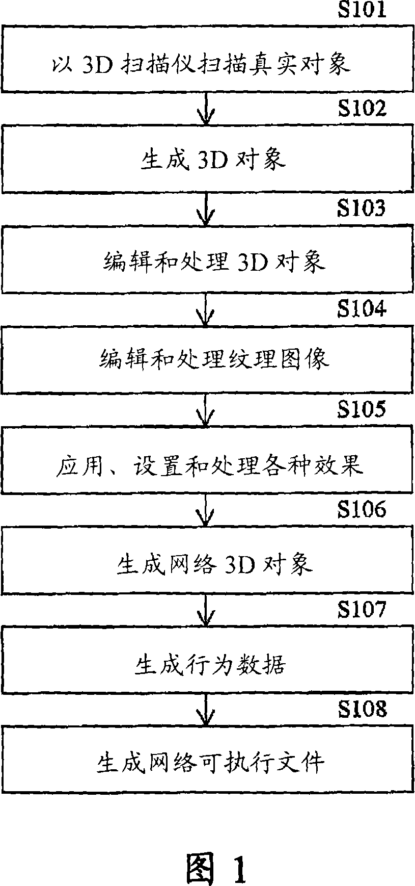
[0055] FIG. 1 is a flowchart showing steps in processing performed by the 3D image generation and display system according to the first embodiment of the present invention.

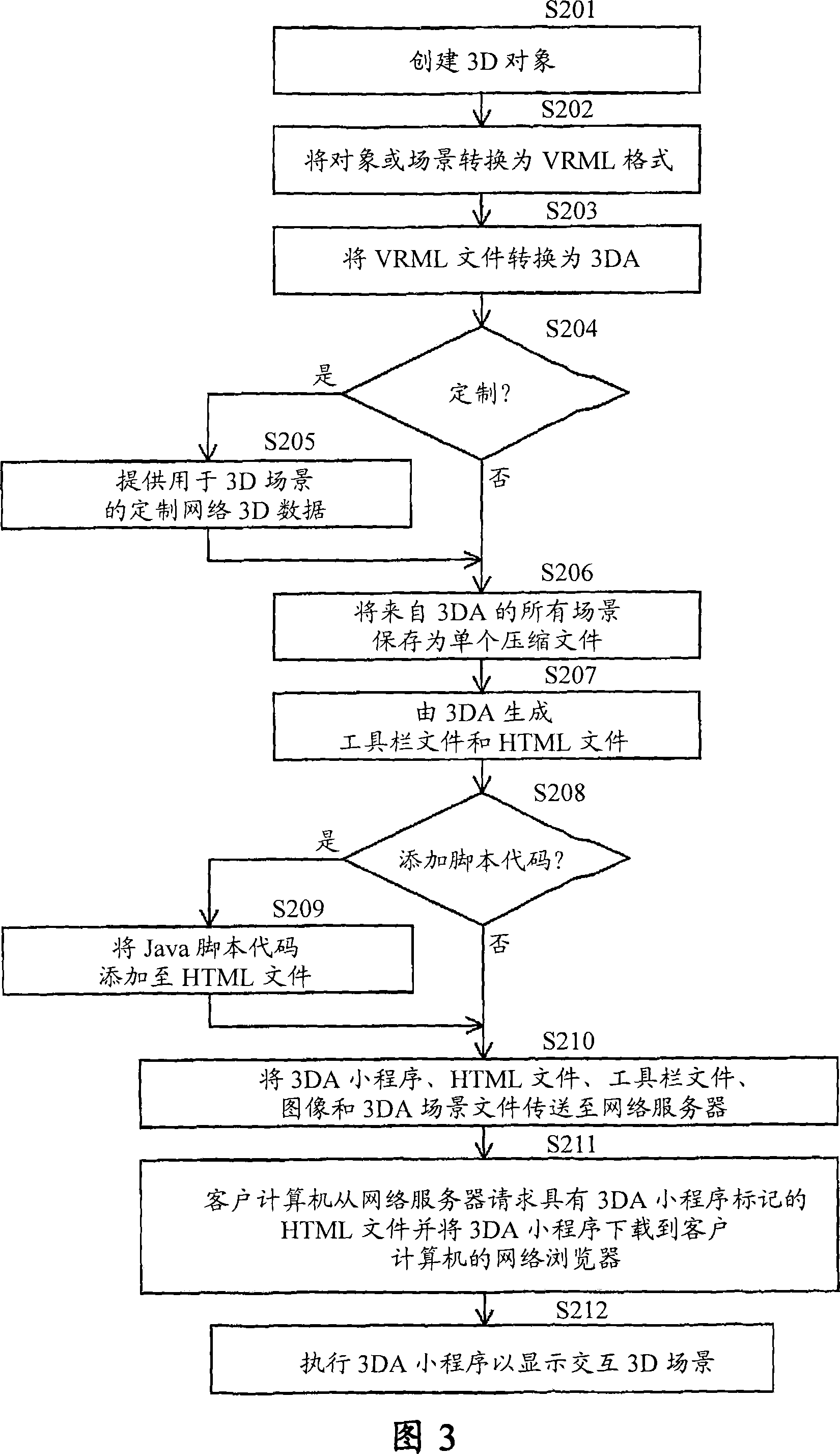
[0056] In the process of FIG. 1 described below, a 3D scanner described later is used to form a plurality of 3D images. A 3D object is generated from a 3D image and converted into a standard virtual reality modeling language (VRML: language for describing 3D graphics) format. The converted 3D object in the output VRML file is subjected to various processes for generating a web 3D object and a program file executable on a web browser.

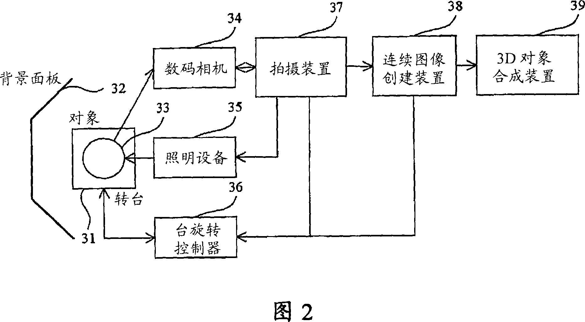
[0057] First, for example, a 3D scanner of a 3D object generation device using a digital camera captures an image of a real object, obtaining 24 3D images taken at varying angles of 15 degrees (S101). The 3D object generation means generates a 3D o...


PUM


Abstract

A 3D image generation and display system facilitating the display of high-quality images in a Web browser comprises means for creating 3D images from a plurality of different images and computer graphics modeling and generating a 3D object from these images that has texture and attribute data; means for converting and outputting the 3D object as a 3D description file in a 3D graphics descriptive language; means for extracting a 3D object and textures from the 3D description file, setting various attribute data, and editing and processing the 3D object to introduce animation or the like and assigning various effects; means for generating various Web-based 3D objects from the 3D data files produced above that are compressed to be displayed in a Web browser and generating behavior data to display 3D scenes in a Web browser with animation; and means for generating an executable file comprising a Web page and Web-based programs such as scripts, plug-ins, and applets for drawing and displaying 3D scenes in a Web browser.

Description

technical field [0001] The present invention relates to a 3D image generation and display system that generates 3D objects for displaying various photographic images and computer graphics models in three dimensions (3D), and for editing and processing for rendering and displaying on web browsers A 3D object for a 3D scene. Background technique [0002] There are various known systems in the field for creating 3D objects for use in 3D displays. One such technique using a 3D scanner for modeling and displaying 3D objects is known in the art as light sectioning (implemented by projecting a slit of light) and the like. This method uses a CCD camera to capture points or lines of light projected onto an object by a laser beam or other light source and uses the principle of triangulation to measure the distance from the camera to perform 3D modeling. [0003] FIG. 13( a ) is a schematic diagram showing a conventional 3D modeling apparatus using a light section method. [0004] A...

Claims


Application Information

Patent Timeline
Patent Type & Authority Applications(China)
IPC IPC(8): G06T15/00G06T17/00G06T17/40H04N13/00G06T13/20
Inventor 伊藤正裕
Owner YAPPA CORP
Why Eureka
Try Eureka