AI technical title is built by Patsnap AI team. It summarizes the technical point description of the patent document.
A technology for pneumatic tires, tires, applied in tire parts, tire tread/tread pattern, transportation and packaging, etc.
Active Publication Date: 2012-05-23
TOYO TIRE & RUBBER CO LTD
View PDF1 Cites 0 Cited by
Summary
Abstract
Description
Claims
Application Information
AI Technical Summary
This helps you quickly interpret patents by identifying the three key elements:
Problems solved by technology
Method used
Benefits of technology
Problems solved by technology
[0003] However, when increasing the number of sipe lines to increase the sipe density, there will be such a problem: although the number of edges is increased, the overall The reduced rigidity of the sipe will cause excessive collapse of the sipe, which will weaken the edge effect. In addition, the ground contact area will become smaller, which will reduce the driving performance on ice and snow roads
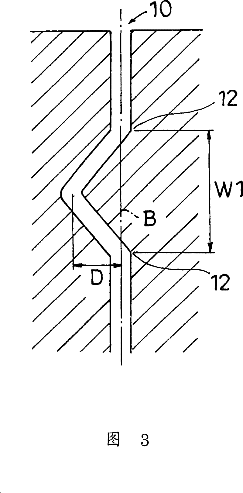
In this sipe, since concave engaging portions are respectively provided on the outer top and the inner top, the effect of restraining the movement of the block piece in the front-rear direction is strong, and conversely, the effect of restraining its movement in the lateral direction is weak.
Method used
Image
Click on the blue label to locate the original text in one second.
Reading with bidirectional positioning of images and text.
Examples
Embodiment approach
[0059] Next, other embodiments of the present invention will be described.
[0060] (1) Although the above-mentioned embodiment shows that the figure 1 The blocks of the shown shape are examples, but the blocks are not limited to this shape, and may be substantially square, parallelogram, V-shaped, pentagonal, or curved-based blocks. In addition, instead of the blocks, ribs extending linearly in the tire circumferential direction, ribs extending zigzag in the tire circumferential direction, lugs, or the like may be formed.
[0061] (2) Although the above embodiment shows an example in which multiple rows of sipe are formed toward the tire width direction, the formation direction of the sipe (central line direction) may be a direction inclined with respect to the tire width direction. However, from the viewpoint of both the turning performance and the braking performance of the tire, the angle between the sipe forming direction and the tire width direction is preferably 0±45°...
Embodiment
[0069] Next, examples and the like which specifically show the configuration and effects of the present invention will be described. In addition, each performance evaluation of the tire was performed as follows.
[0070] (1) Braking performance on icy and snowy roads
[0071] Install the tires on a real vehicle (3000cc class FR sedan produced in Japan), drive it on a frozen road with a load of 1 person, and apply braking force at a speed of 40km / h to activate the ABS. The index evaluation is based on the braking distance at this time. In addition, the evaluation is indicated by an index display when the conventional product (comparative example 1) is 100, and the larger the numerical value, the better the result.
[0072] (2) Turning performance on icy and snowy roads
[0073] The tire is mounted on the same actual vehicle as in (1) above, and it is driven on the same road surface with a double-button curve (8-shaped curve: a circle of R = 25m) under the load condition of o...
Embodiment 1
[0085] for figure 1 The tread pattern shown is formed in the area inside the mounting figure 2 The first sipe shown (same size as Comparative Example 2) is formed in the area outside the mounting Figure 5 The second sipe shown (the size is the same as that of Comparative Example 3) was used to produce a radial tire with a specification of 205 / 65R15. Table 1 shows the results of the performance evaluations described above using this tire.
PUM
Abstract
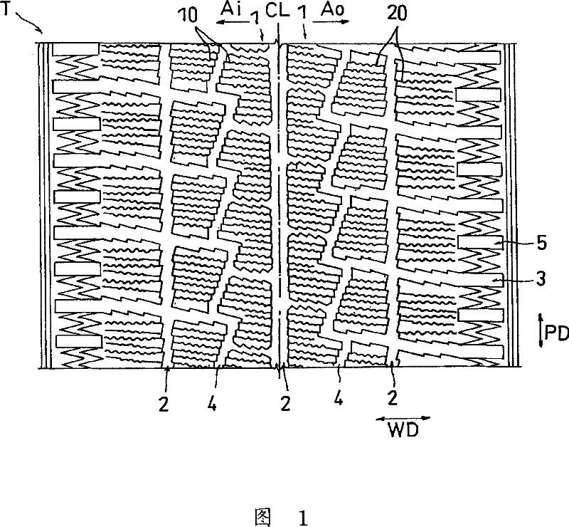
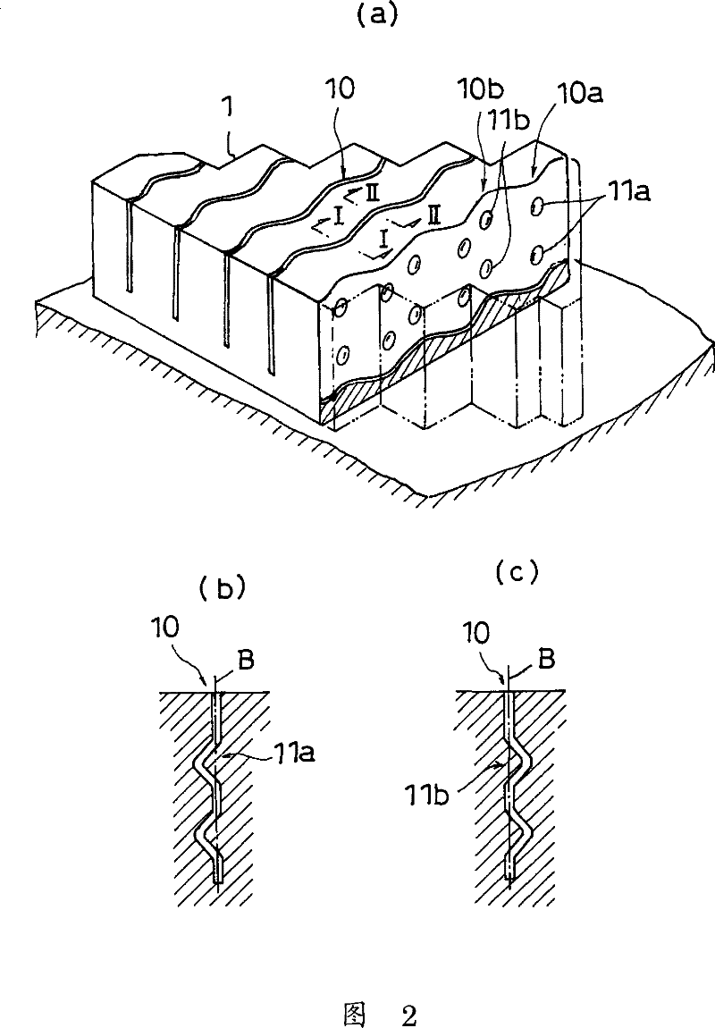
A pneumatic tire simultaneously satisfying both on-ice turning performance and ice braking performance and also simultaneously satisfying both dry turning performance and dry braking performance. The pneumatic tire has a tread pattern (T) having land sections such as blocks (1) in which sipes (10) are formed. First sipes (10) are provided in a region (Ai) on the inner side, in the direction of installation of the tire on the vehicle, of a tire equator line (CL), and second sipes (20) are provided in a region (Ao) on the outer side of the tire equator line (CL). The first sipes (10) each have a recessed or projected engagement section in a cross-section parallel to the tire equator line (CL). In each second sipe (20), an inner wall surface extending in a tire width direction (WD) or in a direction inclined from the tire width direction has rows of grooves and ridges, and each row has a portion inclined in the direction where the sipe are formed.
Description
Technical field [0001] The present invention involves an inflatable tire with tire pattern, which is especially suitable for inlayless tires (tires in winter). The tire pattern forms a so -called three -dimensional knife trough pattern. Background technique [0002] In the past, for the purpose of improving the ice and snow pavement without nail -free tires, there was a structure that configured multiple knife trough patterns in various departments (central ministry, connection (Media) department, and tire shoulder.By forming such a knife slot pattern in the pattern, the edge effect, water removal effect, and condensation effect are improved. Therefore, in recent years, it has inclined to increase the number of knife trough patterns. [0003] However, when increasing the number of knife groove patterns to increase the density of the knife slot pattern, this problem will occur: Although the number of edges is increased, due to the overall rigidity of the pattern block, the tank pa...
Claims
Application Information
Patent Timeline
Application Date:The date an application was filed.
Publication Date:The date a patent or application was officially published.
First Publication Date:The earliest publication date of a patent with the same application number.
Issue Date:Publication date of the patent grant document.
PCT Entry Date:The Entry date of PCT National Phase.
Estimated Expiry Date:The statutory expiry date of a patent right according to the Patent Law, and it is the longest term of protection that the patent right can achieve without the termination of the patent right due to other reasons(Term extension factor has been taken into account ).
Invalid Date:Actual expiry date is based on effective date or publication date of legal transaction data of invalid patent.

