Pneumatic tire

A technology of pneumatic tires and tires, applied in tire parts, tire treads/tread patterns, transportation and packaging, etc. The effect of enhancing the combined effect, improving the braking performance, and suppressing the movement in the lateral direction

Active Publication Date: 2008-06-04
TOYO TIRE & RUBBER CO LTD
View PDF5 Cites 14 Cited by
  • Summary
  • Abstract
  • Description
  • Claims
  • Application Information

AI Technical Summary

Problems solved by technology

[0003] However, when increasing the number of sipe lines to increase the sipe density, there will be such a problem: although the number of edges is increased, the overall The reduced rigidity of the sipe will cause excessive collapse of the sipe, which will weaken the edge effect. In addition, the ground contact area will become smaller, which will reduce the driving performance on ice and snow roads
In this sipe, since concave engaging portions are respectively provided on the outer top and the inner top, the effect of restraining the movement of the block piece in the front-rear direction is strong, and conversely, the effect of restraining its movement in the lateral direction is weak.

Method used


Image

  • Pneumatic tire
  • Pneumatic tire
  • Pneumatic tire

Examples


Embodiment approach

[0057] Next, other embodiments of the present invention will be described.

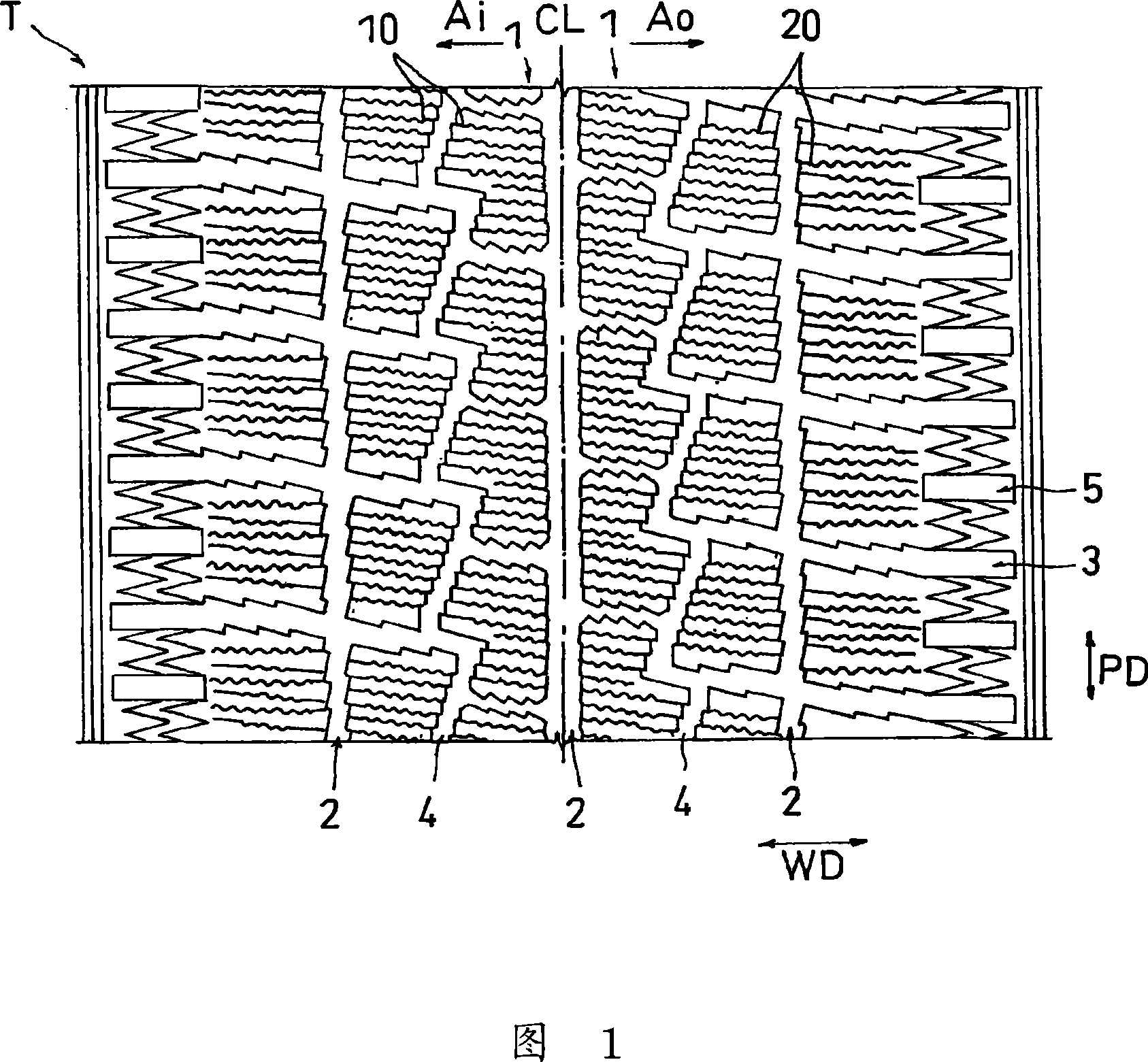
[0058] (1) Although the above-mentioned embodiment has shown an example in which the blocks are formed in the shape shown in FIG. Pattern blocks in a curved tone. In addition, instead of the blocks, ribs extending linearly in the tire circumferential direction, ribs extending zigzag in the tire circumferential direction, lugs, or the like may be formed.

[0059] (2) Although the above embodiment shows an example in which multiple rows of sipe are formed toward the tire width direction, the formation direction of the sipe (central line direction) may be a direction inclined with respect to the tire width direction. However, from the viewpoint of both the turning performance and the braking performance of the tire, the angle between the sipe forming direction and the tire width direction is preferably 0±45°, more preferably 0±20°, even more preferably 0±10° .

[0060] (3) Although the above embodimen...

Embodiment

[0067]Next, examples and the like which specifically show the configuration and effects of the present invention will be described. In addition, each performance evaluation of the tire was performed as follows.

[0068] (1) Braking performance on icy and snowy roads

[0069] Install the tires on a real vehicle (3000cc class FR sedan produced in Japan), drive it on a frozen road with a load of 1 person, and apply braking force at a speed of 40km / h to activate the ABS. The index evaluation is based on the braking distance at this time. In addition, the evaluation is indicated by an index display when the conventional product (comparative example 1) is 100, and the larger the numerical value, the better the result.

[0070] (2) Turning performance on icy and snowy roads

[0071] The tire is mounted on the same actual vehicle as in (1) above, and it is driven on the same road surface with a double-button curve (8-shaped curve: a circle of R = 25m) under the load condition of on...

Embodiment 1

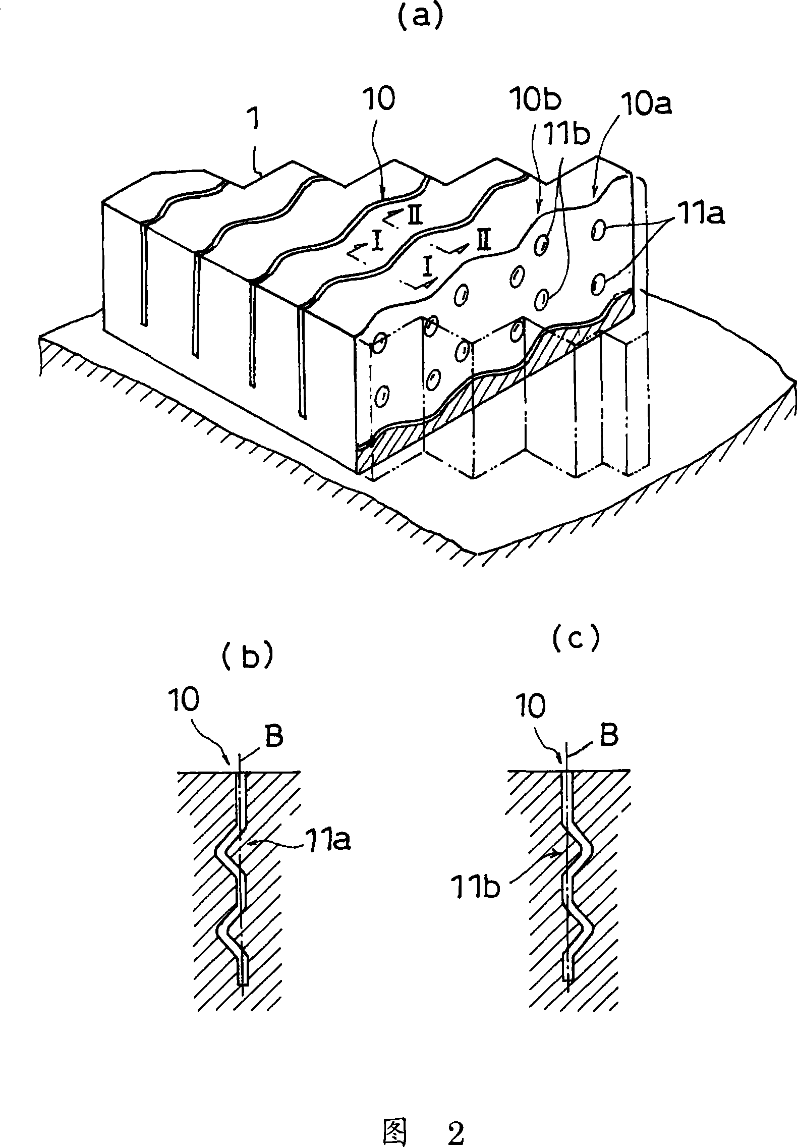
[0083] For the tread pattern shown in Fig. 1, the first sipe shown in Fig. 2 (same size as in Comparative Example 2) is formed in the mounting inner region, and the second siping shown in Fig. 5 is formed in the mounting outer region Pattern (the size is identical with comparative example 3), makes the radial tire that specification is 205 / 65R15. Table 1 shows the results of the performance evaluations described above using this tire.


PUM


Abstract

A pneumatic tire simultaneously satisfying both on-ice turning performance and ice braking performance and also simultaneously satisfying both dry turning performance and dry braking performance. The pneumatic tire has a tread pattern (T) having land sections such as blocks (1) in which sipes (10) are formed. First sipes (10) are provided in a region (Ai) on the inner side, in the direction of installation of the tire on the vehicle, of a tire equator line (CL), and second sipes (20) are provided in a region (Ao) on the outer side of the tire equator line (CL). The first sipes (10) each have a recessed or projected engagement section in a cross-section parallel to the tire equator line (CL). In each second sipe (20), an inner wall surface extending in a tire width direction (WD) or in a direction inclined from the tire width direction has rows of grooves and ridges, and each row has a portion inclined in the direction where the sipe are formed.

Description

technical field [0001] The present invention relates to a pneumatic tire particularly suitable as a studless tire (winter tire) having a tread pattern formed with a land contact portion having a so-called three-dimensional sipe. Background technique [0002] Conventionally, a structure in which a plurality of sipes are arranged in each part (center part, mediate part, shoulder part) of a tire tread is known for the purpose of improving the driving performance on ice and snow roads of a studless tire. By forming such sipe in the block, the edge effect, the dewatering effect, and the condensation effect are improved, and therefore the number of sipe lines tends to increase in recent years. [0003] However, when increasing the number of sipe lines to increase the sipe density, there is a problem that although the number of edges is increased, the sipe collapses excessively due to the decrease in the overall rigidity of the block, which weakens the edge effect , In addition, t...

Claims


Application Information

Patent Timeline
Patent Type & Authority Applications(China)
IPC IPC(8): B60C11/117
CPCB60C2011/1213B60C11/12B60C11/1218B60C11/0306
Inventor 大桥稔之
Owner TOYO TIRE & RUBBER CO LTD
Why Eureka
Try Eureka