Optical plate

An optical plate and transparent layer technology, applied in the field of optical plates, can solve the problems of reducing light utilization rate, light energy consumption and loss increase, etc., to achieve the effects of improving light utilization rate, reducing optical transmission loss, and reducing interface loss

Inactive Publication Date: 2008-06-04
HONG FU JIN PRECISION IND (SHENZHEN) CO LTD +1
View PDF0 Cites 8 Cited by
  • Summary
  • Abstract
  • Description
  • Claims
  • Application Information

AI Technical Summary

Problems solved by technology

[0004] However, in the prior art, the diffusion plate 13 and the prism sheet 15 are prepared separately, which makes the diffusion plate 13 and the prism sheet 15 independent of each other. During use, although the diffusion plate 13 and the prism sheet 15 can be in close contact, there is still a gap between the diffusion plate 13 and the prism sheet 15. There will be a fine air barrier layer; when the light propagates between the diffuser plate 13 and the prism sheet 15 and passes through the air barrier layer, the light will easily occur at the interface between the air barrier layer and the diffuser plate 13 and the prism sheet 15. Interface reflection and other effects increase the consumption and loss of light energy, thereby reducing the utilization rate of light

Method used


Image

  • Optical plate
  • Optical plate
  • Optical plate

Examples


Embodiment Construction

[0016] The optical plate will be further described in detail with reference to the accompanying drawings and embodiments.

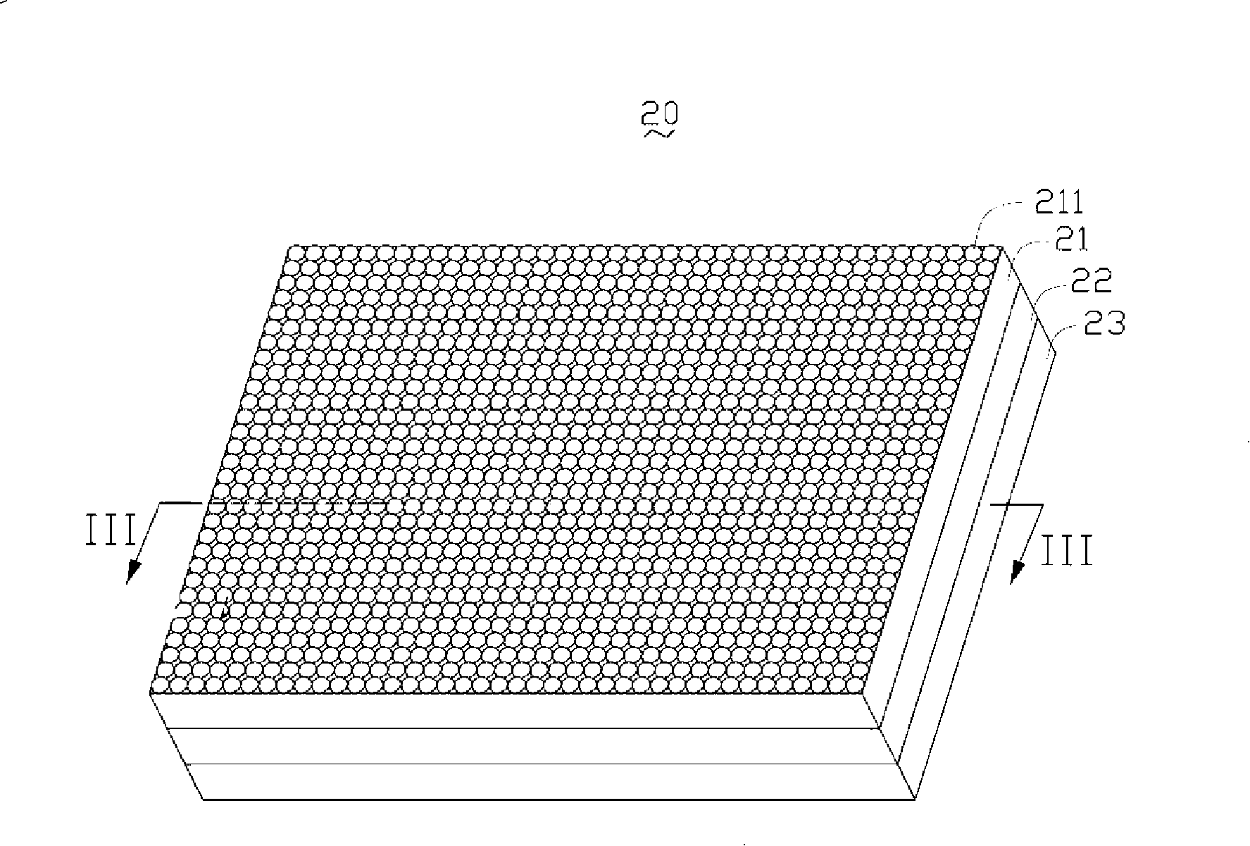
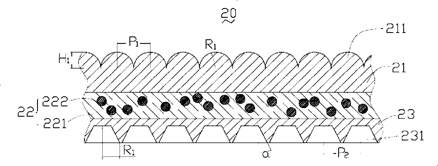
[0017] See figure 2 and image 3 , the optical plate 20 provided by the preferred embodiment 1 of the present invention includes an integrally formed diffusion layer 22 and a first transparent layer 21 and a second transparent layer 23 respectively located on two opposite surfaces of the diffusion layer 22, that is, injection molding through a mold Form the first transparent layer 21, then inject molding on the first transparent layer 21 to form the diffusion layer 22, and then injection molding on the diffusion layer 22 to form the second transparent layer 23, it can be understood that the first transparent layer 21, the diffusion layer 22 , The formation sequence of the second transparent layer 23 can also be appropriately changed, but the diffusion layer 22 needs to be located between the first transparent layer 21 and the second transparent layer 23...


PUM

PropertyMeasurementUnit
thicknessaaaaaaaaaa
distanceaaaaaaaaaa

Abstract

The invention discloses an optic plate, comprising a first transparent layer, a diffusion layer and a second transparent layer which are formed integrally, wherein the diffusion layer is positioned between the first transparent layer and the second transparent layer; the diffusion layer contains transparent resin and diffusing particles dispersed in the transparent resin; the external surface of the first transparent layer opposite to the diffusion layer is provided with a plurality of spherical bulges; the external surface of the second transparent layer opposite to the diffusion layer is provided with a plurality of cone shaped grooves. The optic plate has the advantage of improving the utilization rate of light rays.

Description

technical field [0001] The invention relates to an optical plate for a backlight module, in particular to a composite optical plate. Background technique [0002] Liquid crystal display devices are widely used in electronic products such as personal digital assistants, notebook computers, digital cameras, mobile phones, and LCD TVs. However, since the liquid crystal display device itself cannot emit light, it needs a backlight module to produce a display function. [0003] See figure 1 , a schematic cross-sectional view of a backlight module using an existing optical plate. The backlight module 10 includes a reflector 11 , and above the reflector 11 sequentially includes a plurality of light sources 12 , a diffusion plate 13 and a transparent prism sheet 15 . Among them, the diffusion plate 13 generally contains methyl methacrylate fine particles, and the methyl methacrylate fine particles serve as diffusing particles for diffusing light. The prism sheet 15 has a V-shape...

Claims


Application Information

Patent Timeline
Patent Type & Authority Applications(China)
IPC IPC(8): G02B5/02G02B1/04G02F1/1335
CPCG02B5/0278G02F1/133606G02B5/0215G02B5/0242
Inventor 许东明章绍汉
Owner HONG FU JIN PRECISION IND (SHENZHEN) CO LTD
Why Eureka
Try Eureka