
LCD display panel and device

A liquid crystal display panel and liquid crystal layer technology, which is applied to instruments, nonlinear optics, optics, etc., can solve the problems of easy damage to the sealant of the liquid crystal display panel, and achieve the effects of reducing impact force, reducing damage, and slowing the diffusion speed of liquid crystal.

Inactive Publication Date: 2008-06-04
INNOCOM TECH (SHENZHEN) CO LTD +1
View PDF0 Cites 24 Cited by
  • Summary
  • Abstract
  • Description
  • Claims
  • Application Information

AI Technical Summary

Problems solved by technology

[0008] In order to solve the above-mentioned problem that the frame glue of the liquid crystal display panel is easily damaged, it is necessary to provide a liquid crystal display panel that is not easy to damage the frame glue

Method used

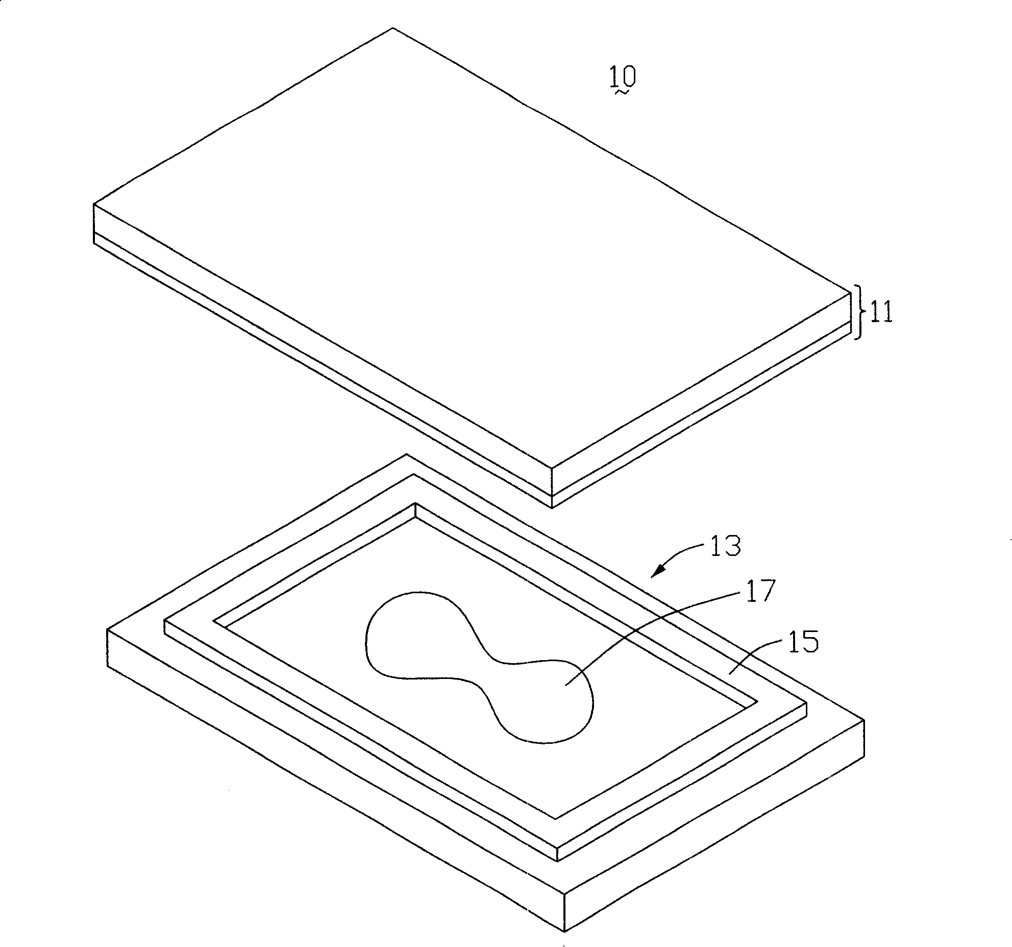
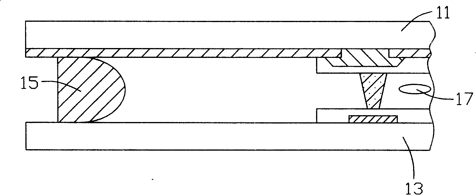

Image

  • LCD display panel and device
  • LCD display panel and device
  • LCD display panel and device

Examples


Embodiment Construction

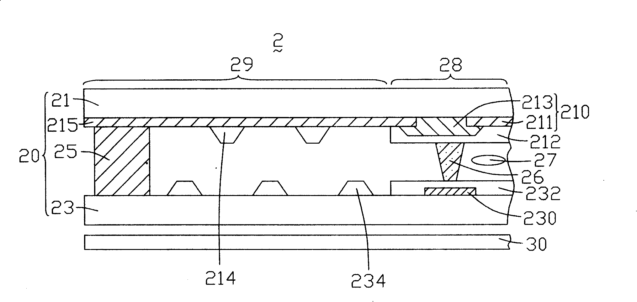
[0020] see image 3 , is a partial cross-sectional schematic diagram of the first embodiment of the liquid crystal display of the present invention. The liquid crystal display 2 includes a liquid crystal display panel 20 and a backlight module 30 , and light emitted from the backlight module 30 enters the liquid crystal display panel 20 .

[0021] The LCD panel 20 has a display area 28 and a non-display area 29 located around the display area 28 . The liquid crystal display panel 20 includes a first substrate 21 , a second substrate 23 , a sealant 25 , a plurality of spacers 26 and a liquid crystal layer 27 . The second substrate 23 is opposite to the first substrate 21 . The sealant 25 is sandwiched between the second substrate 23 and the first substrate 21 , disposed in the non-display area 29 , and forms a liquid crystal cell (not shown) with the second substrate 23 and the first substrate 21 . The plurality of spacers 26 are distributed in the liquid crystal cell at int...


PUM


Abstract

The present invention relates to a liquid crystal display panel having a display area. The liquid crystal display panel comprises a first base plate, a second base plate, a glue frame and a liquid crystal layer. The second base plate and the first base plate are oppositely arranged; the glue frame is used to joint the first base plate and the second base plate; the first base plate and the second base plate form a liquid crystal box; the liquid crystal layer is arranged inside the liquid crystal box, wherein, the first base plate and the second base plate respectively comprise a plurality of protuberances which are arranged between the glue frame and the display area. The present invention also provides a liquid crystal display adopting the liquid crystal display panel. The liquid crystal display panel and the liquid crystal display can effectively decrease the damage phenomena of the glue frame.

Description

technical field [0001] The present invention relates to a liquid crystal display panel and a liquid crystal display, in particular to a dripping type liquid crystal display panel and a liquid crystal display. Background technique [0002] The structure of the liquid crystal panel generally includes two glass substrates, a sealant coated between the two glass substrates, and liquid crystal poured into the space formed by the sealant and the two glass substrates. [0003] There are generally two methods for pouring liquid crystal molecules into the space formed by the sealant and the two glass substrates. One is the injection method, that is: first apply the frame glue on a glass substrate, and set one or more liquid crystal injection openings on the frame glue; then attach another glass substrate to it, and apply the frame glue Curing to make the two glass substrates firmly bond; then place the laminated semi-finished product above the liquid crystal in a vacuum environment,...

Claims


Application Information

Patent Timeline
Patent Type & Authority Applications(China)
IPC IPC(8): G02F1/1339G02F1/1333
CPCG02F1/1339
Inventor 詹家明卓宏升萧坤星
Owner INNOCOM TECH (SHENZHEN) CO LTD
Learn More