Flow rate measuring device

一种流速测量、流体的技术,应用在流速测量装置领域,能够解决流速检测件输出线性度降低、减小装置的尺寸存在限制、难高精度的测量等问题,达到减小尺寸、避免故障、高测量精度的效果

Active Publication Date: 2008-06-04
OMRON CORP
View PDF1 Cites 7 Cited by
  • Summary
  • Abstract
  • Description
  • Claims
  • Application Information

AI Technical Summary

Problems solved by technology

Thus there is a limit in reducing the size of the device
In particular, if the flow rate increases, the output linearity of the flow rate detector decreases, and it becomes difficult to perform high-precision measurement

Method used


Image

  • Flow rate measuring device
  • Flow rate measuring device
  • Flow rate measuring device

Examples


Embodiment Construction

[0078] Embodiments of the present invention will be described with reference to the drawings from FIG. 1 to FIG. 16 .

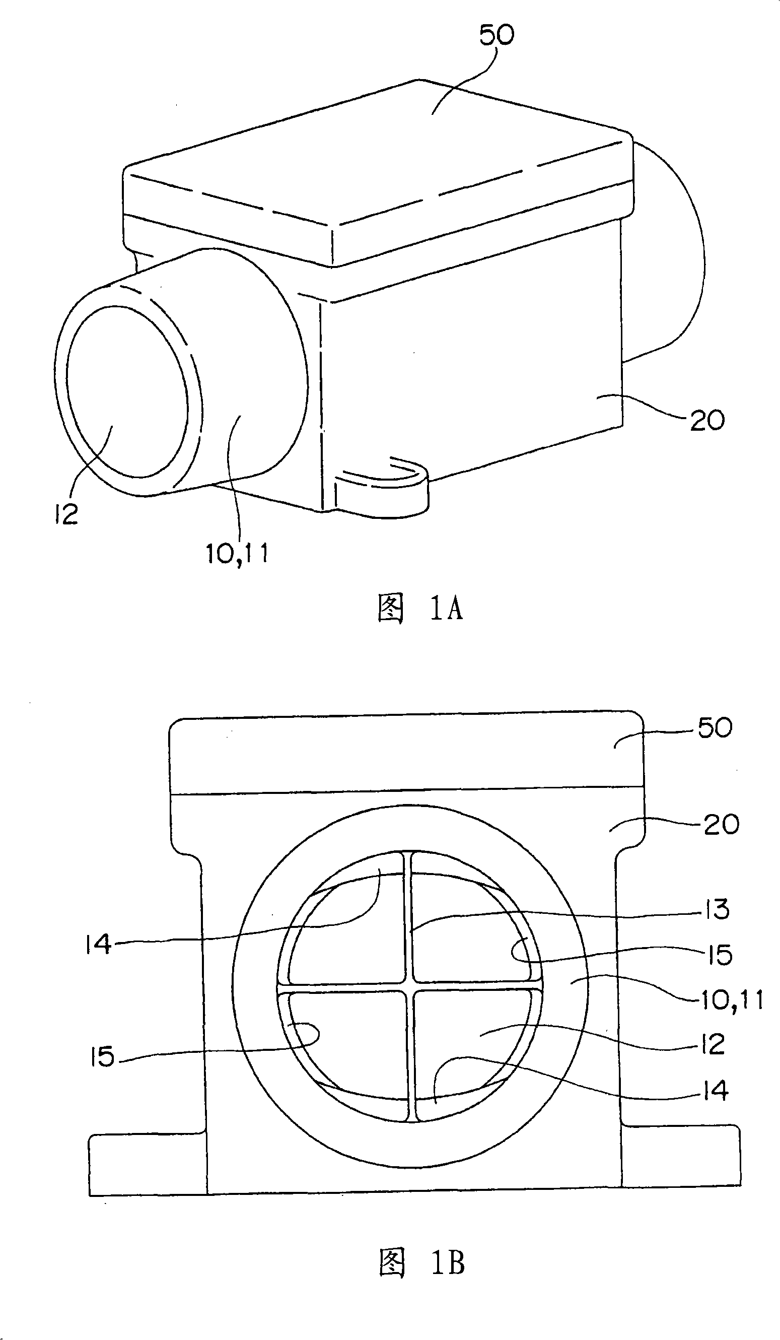
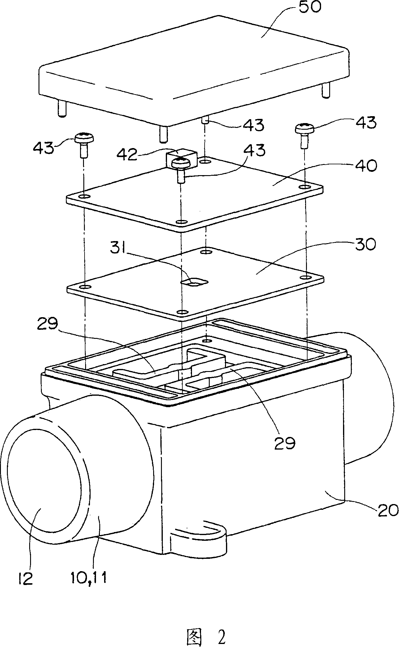
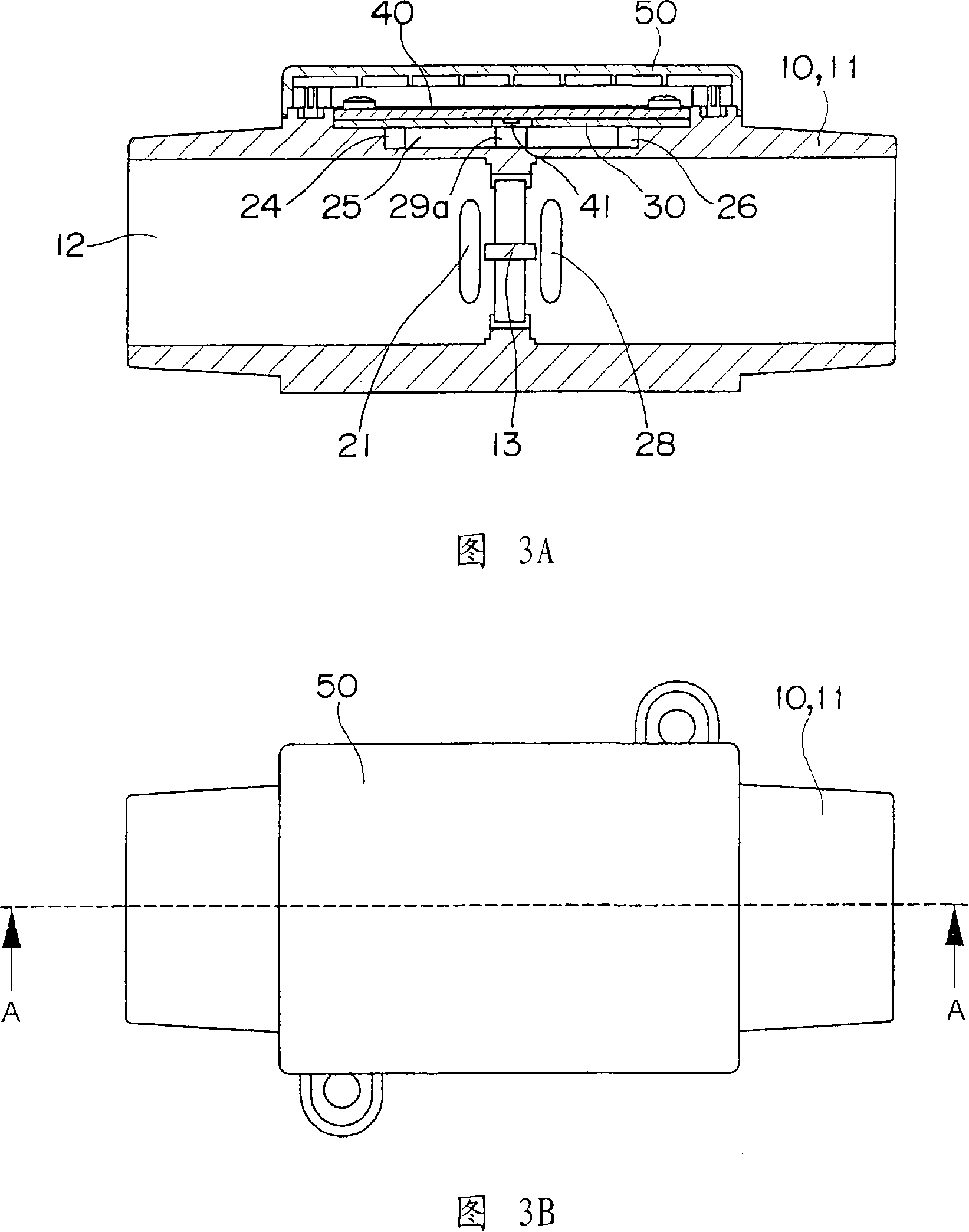
[0079] As shown in FIGS. 1 and 2 , the flow rate measuring device of this embodiment includes: a base body 10 integrally molded with a secondary flow channel block 20 for forming a secondary flow channel on the outer peripheral surface of the main flow tube 11 channel; a sealing plate 30 having a measuring hole 31 at its center portion and sealing the opening of the secondary flow channel block 20; a circuit board 40 having a flow velocity detecting member 41 to be inserted through the measuring hole 31 at its center and its lower surface, which stacked on the sealing plate 30 ; and a cover 50 for covering the opening of the secondary flow channel block 20 . The sealing plate 30 and the circuit board 40 are fixed to the secondary flow channel block 20 by screws 43 .

[0080] The base body 10 is provided with a cross-shaped orifice 13 at a central portion of ...


PUM


Abstract

The invention discloses a flow rate measuring device which is small in size and in which dust and the like can hardly pass through, has high measurement accuracy, and has small pressure loss. The secondary flow channel includes: a guide channel 22, wherein the upstream side is communicated with the guide port 21 used as the first split point, and the downstream side is used as the second split point 20a; the first flow channel 23, wherein the upstream side is at the second split point. The diversion point 20a is divided and formed from the diversion channel 22 so that it is parallel to the main flow channel 12, and the downstream side communicates with the discharge port 28; 22 is divided and formed so as to cross the main flow channel 12; and the third flow channel (detection flow channel) 25, wherein the upstream side communicates with the downstream side of the second flow channel 24, the flow velocity detection member is provided, and the downstream The side communicates with the discharge port 28 .

Description

technical field [0001] The present invention relates to a flow rate measuring device, such as a small flow rate measuring device, for industrial equipment for monitoring air flow rate in factories, for medical equipment such as sleep apnea syndrome medical devices. Background technique [0002] Generally, in a flow rate measuring device, since the flow rate decreases to the measurable range of the flow rate detection member, in a straight pipe type flow rate measuring device that directly measures a relatively large flow rate, the pipe diameter needs to be increased. There is thus a limit in reducing the size of the device. In particular, if the flow rate increases, the output linearity of the flow rate detection element decreases, and it becomes difficult to perform high-precision measurement. Therefore, in order to improve the measurement accuracy as well as to reduce the size, a small flow rate measuring device has been proposed in which the main flow channel is provided...

Claims


Application Information

Patent Timeline
Patent Type & Authority Applications(China)
IPC IPC(8): G01F1/00G01F1/68
CPCG01F5/00G01F1/6842
Inventor 上田直亚野添悟史下元康司
Owner OMRON CORP
Why Eureka
Try Eureka