Shear type hoisting device

A scissor type, bottom plate technology, applied in the direction of lifting device, lifting frame, etc., can solve the problems of large lifting height, low lifting resolution, large driving force, etc., to achieve the effect of rapid lifting movement, ensuring flexibility, and improving stability

Inactive Publication Date: 2008-06-11
SHANGHAI MICRO ELECTRONICS EQUIP (GRP) CO LTD
View PDF0 Cites 56 Cited by
  • Summary
  • Abstract
  • Description
  • Claims
  • Application Information

AI Technical Summary

Problems solved by technology

The scissor lifting device in the prior art generally has a small minimum height, a large lifting height, and a large external dimension. During the lifting process, the lifting speed is the same as the falling speed, and there is no slow rising and fast falling function. When lifting, the driving force required is larger
In addition, the scissor lifting device in

Method used


Image

  • Shear type hoisting device
  • Shear type hoisting device

Examples


Embodiment Construction

[0018] The scissor lifting device of the present invention will be described in detail below in conjunction with the accompanying drawings and specific embodiments.

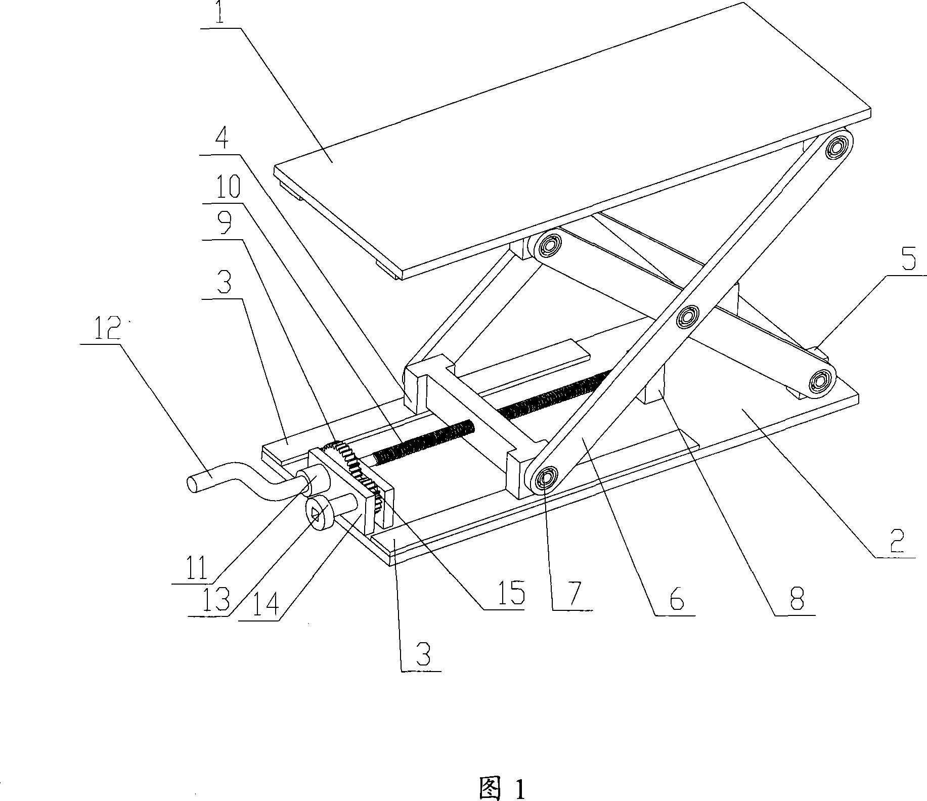
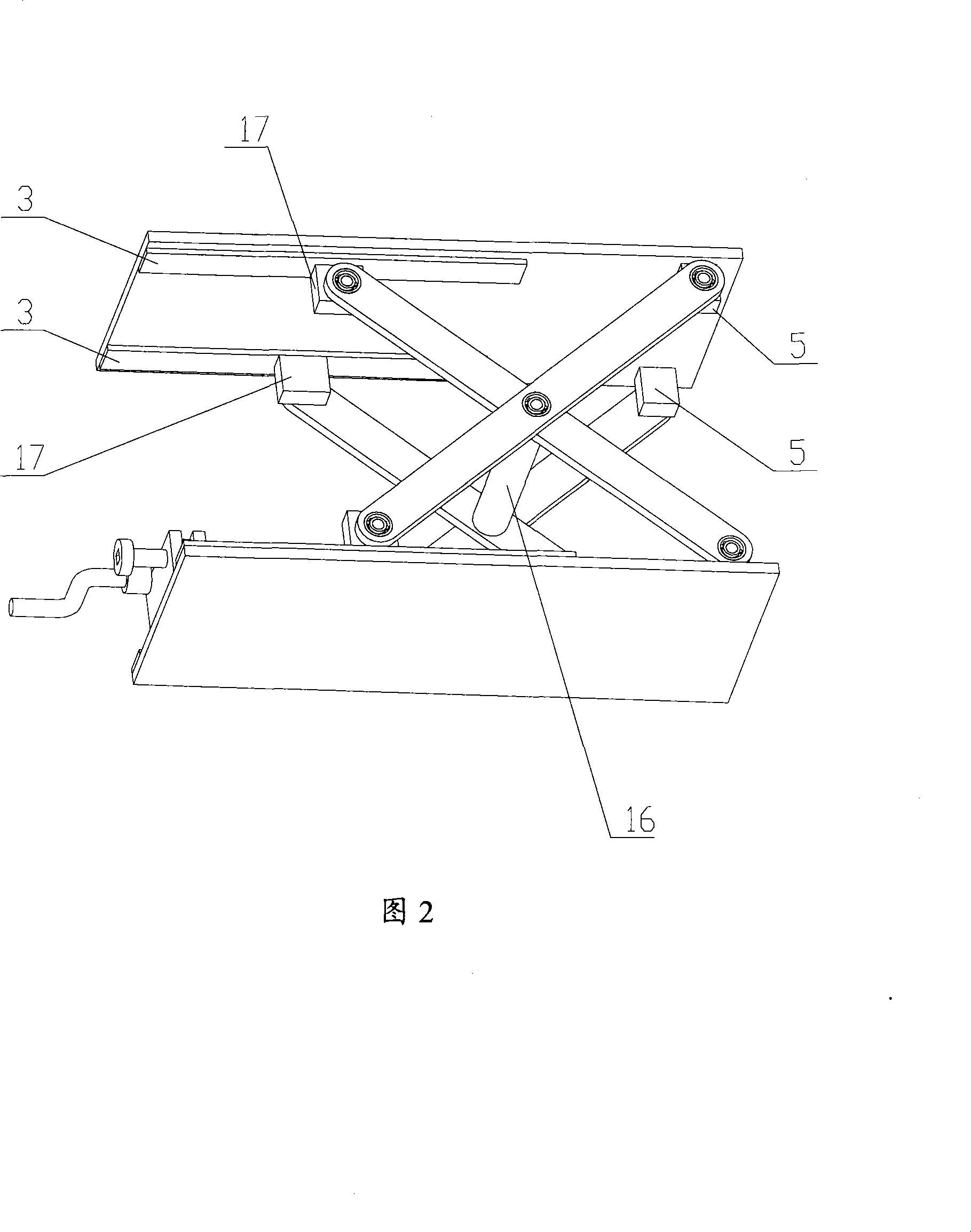
[0019] 1 and 2, the present invention includes: bearing plate 1, bottom plate 2, guide rail 3, driving slider 4, fixed shaft seat 5, connecting rod 6, bearing 7, screw seat 8, large gear 9, screw 10 , Coarse adjustment knob 11, drive crank 12, fine adjustment knob 13, gear bracket plate 14, pinion 15, pin shaft 16, slide block 17.

[0020] The bearing plate 1 and the base plate 2 are connected by two sets of intersecting connecting rods 6 in an X shape, and four guide rails 3 are respectively installed on both sides of the bearing plate 1 and the base plate 2 in parallel along the longitudinal direction. The driving slider 4 is connected to the two ends of the two co-directional connecting rods 6 through the bearing 7, and can slide along the guide rail 3 on the bottom plate 2, and the slider 17 is connected to t...


PUM


Abstract

The invention provides a scissors lifting device which comprises a loading plate, a bottom plate, two groups of connecting rods which are in X-shaped cross connection and drive elements of connecting rods, wherein the bottom plate is glidingly connected with the lower end of one pair of co-rotating connecting rod of the two groups of the connecting rods through a drive slide block, the loading plate is glidingly connected with the upper end of another pair of the co-rotating connecting rod by a slide block , the lower end of another pair of the co-rotating connecting rod is fixedly connected with the bottom plate, the drive slide block is provided with a screw hole, and a screw rod passes through the screw hole and is meshed with a screw pair of the drive slide block. The drive elements of the connecting rods include a large gear, a small gear, a rough adjusting knot, and a fine adjusting knot, one end of the screw rod is fixed on the bottom plate, the other end of the screw rod is coaxially connected with the big gear, the small gear is meshed with the gear pair of the large gear, the rough adjusting knot is coaxially connected with the large gear, and the fine adjusting knot is coaxially connected with the small gear. The scissors lifting device of the invention has the advantages that frictional force of each joint is small, the loading amount is large, and a loading platform is stable without swinging in the lifting process of the whole device and has the function of slow rising and quick descending.

Description

technical field [0001] The invention relates to a lifting device, in particular to a scissor lifting device. Background technique [0002] Modern production requires precision lifting scissor lifting devices. For example, in the development or integration process of lithography machines, most lithography machine structures need precision lifting to realize the connection of mechanical interfaces or height adjustment and focus adjustment during experiments. Leveling is a precision opto-electromechanical device. During the installation process, there must be no large vibrations, and accurate docking of the mechanical interface must be achieved. The scissor lifting device in the prior art generally has a small minimum height, a large lifting height, and a large external dimension. During the lifting process, the lifting speed is the same as the falling speed, and there is no slow rising and fast falling function. When it is lifted, a larger driving force is required. In addit...

Claims


Application Information

Patent Timeline
IPC IPC(8): B66F7/06B66F7/00
Inventor 肖可云袁志扬严天宏
Owner SHANGHAI MICRO ELECTRONICS EQUIP (GRP) CO LTD
Why Eureka
Try Eureka