
Engine cooling system

An engine cooling and cooling channel technology, applied in the direction of engine cooling, engine components, machines/engines, etc., can solve problems such as increasing engine warm-up time, heat loss, and increasing fuel consumption, reducing heat loss, realizing easy, Design a simple effect

Active Publication Date: 2008-06-11
CHERY AUTOMOBILE CO LTD
View PDF0 Cites 15 Cited by
  • Summary
  • Abstract
  • Description
  • Claims
  • Application Information

AI Technical Summary

Problems solved by technology

However, due to the small circulation, part of the coolant flows through the heater (there is a small radiator inside the heater), which will cause a certain amount of heat loss, which will undoubtedly increase the warm-up time of the engine and increase fuel consumption.

Method used


Image

  • Engine cooling system
  • Engine cooling system

Examples


Embodiment 1

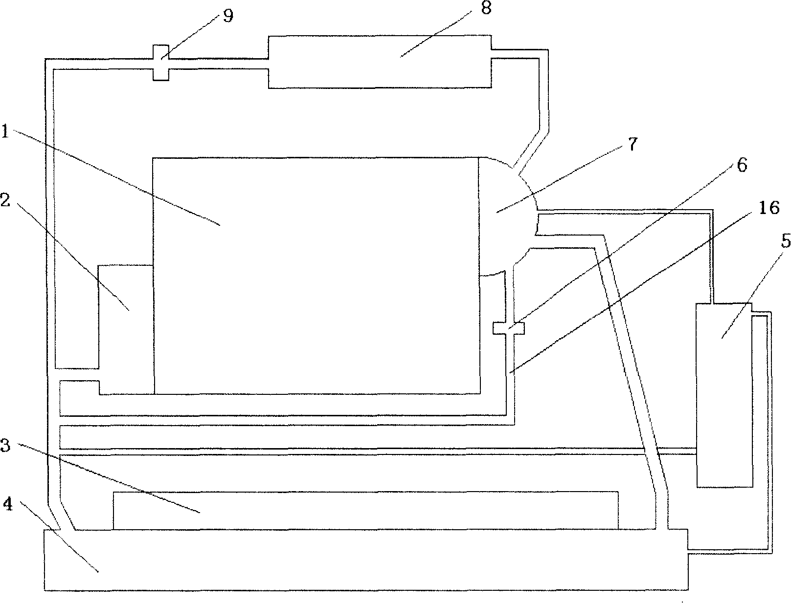
[0015] Example 1 in figure 1 Among them, an engine cooling system mainly includes an engine body water jacket (1), a water pump (2), a radiator (4), a fan (3), a thermostat (7), an expansion tank (5), and a heater for cooling (8) and connecting pipelines; when the engine coolant rises to the set temperature, the main valve of the thermostat (7) is opened, the auxiliary valve is closed, and the water jacket of the engine body (1) and the thermostat (7), Expansion tank (5), radiator (4), water pump (2) pipeline connection and engine body water jacket (1) and thermostat (7), small circulation loop (16), heater radiator (8), The pipes of the water pump (2) are connected together to form a large circulation cooling channel; when the temperature of the engine coolant is lower than the set temperature, the main valve of the thermostat (7) is closed and the auxiliary valve is opened, and the water jacket (1) of the engine body and the thermostat device (7), small circulation circuit ...

Embodiment 2

[0016] Embodiment 2 A shut-off valve (6) with a temperature control function is set in the small circulation loop (16). When the temperature is lower than the set temperature, the shut-off valve is in an open state. When the temperature is higher than the set temperature, the shut-off valve body is off. All the other are with embodiment 1.

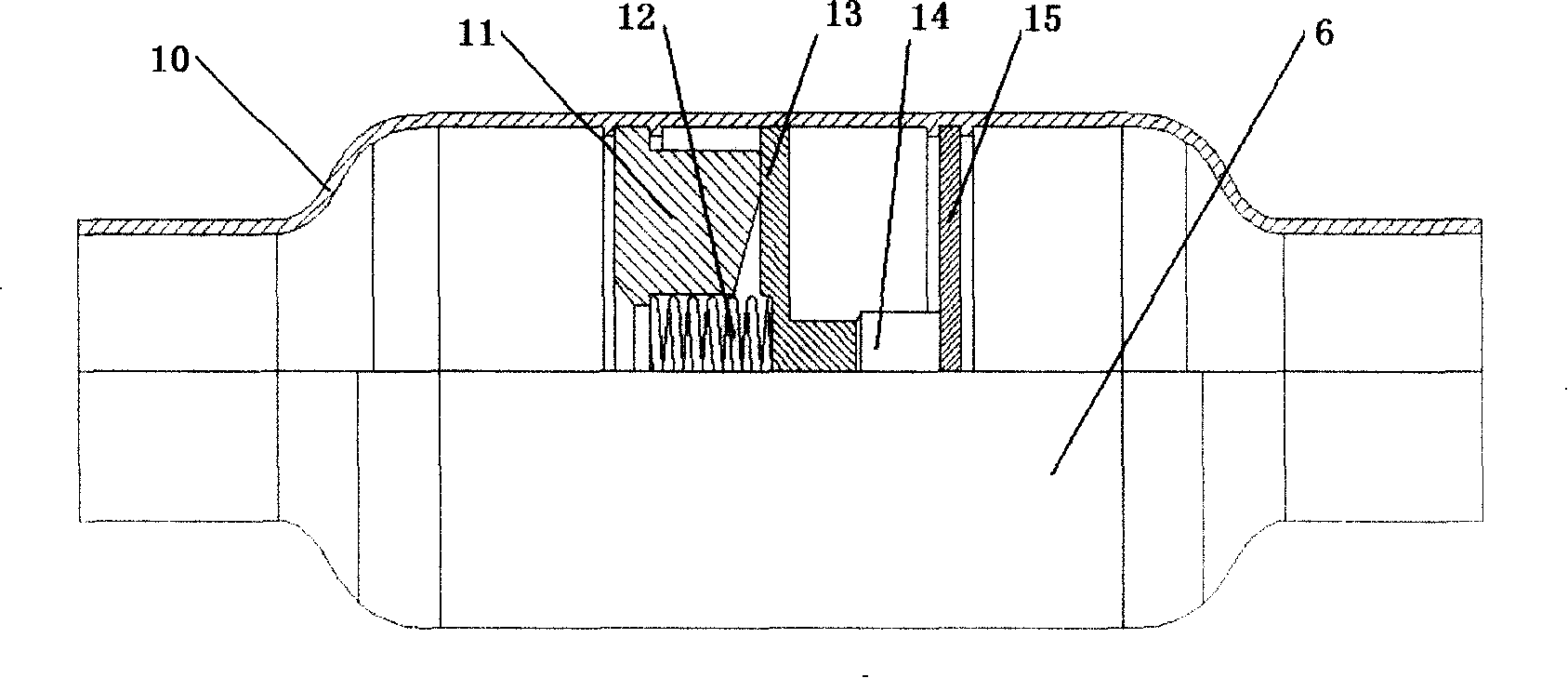
[0017] Above-mentioned shut-off valve body (16), as figure 2 As shown, it is mainly composed of a housing (10), a first fixed plate (11), a second fixed plate (15), a sliding plate and a push rod (13), a medium cavity (14), and a spring (12); The body (10) is fixed in the middle of the fixed disks (11, 15) at both ends of the inlet and outlet, and the spring (12), sliding disk and push rod (13), and the medium chamber (14) are connected in sequence; When the coolant temperature reaches the set temperature, the medium in the medium cavity (14) begins to expand, pushing the sliding plate and the push rod (13), and the linkage compresses t...


PUM


Abstract

An engine cooling system is provided, which comprises an engine body water jacket, a water pump, a radiator, a fan, a thermalstat, an expansion tank, a warm air machine cooler and a connection pipeline. The pipeline of the said components connects together to form a large circulating cooling passage, a small circulating cooling passage and a warm air system pipeline. The invention is characterized in that: a cut-off valve with temperature control function is positioned in the warm air system pipeline; when the engine starts and the temperature of the liquid coolant of engine is lower than the preset temperature, the cut-off valve is placed at the switch-off state. A cut-off valve with temperature control function can also be positioned in a small recycling loop; when the temperature is lower than the preset one, the cut-off valve is placed at switch-on state; when the temperature exceeds the preset one, the cut-off valve is placed at switch-off state. Because two cut-off valves with temperature control function are added, the liquid coolant does not flow through the warm air system before the temperature reaches the preset one, which reduces the heat loss and pre-heat time for the engine in this stage. Therefore, this invention can be best applied in winter or regions of harsh cold.

Description

technical field [0001] The invention relates to a cooling system of a vehicle engine, more specifically to a small circulation of the vehicle engine cooling system and a rapid warm-up system of the water circulation of a heater. Background technique [0002] At present, the forced circulation water cooling system is generally used in automobile engines. It uses a water pump to increase the pressure of cooling water to circulate it in the engine cooling system. [0003] "Automobile Structure" (2nd edition, edited by Guan Wenda of Jilin University, Mechanical Industry Press) discloses a water cooling system. Both the cylinder head and the cylinder block of the water-cooled engine are cast with interconnected water jackets. Under the action of the water pump, the cooling water flows through the cooling water jacket of the cylinder block and the cylinder head to absorb heat, and then flows into the radiator along the water pipe. Using the speed of the car and the strong sucti...

Claims


Application Information

Patent Timeline
IPC IPC(8): F01P3/20F01P7/16
Inventor 朱飞雄
Owner CHERY AUTOMOBILE CO LTD
Features
  • Generate Ideas
  • Intellectual Property
  • Life Sciences
  • Materials
  • Tech Scout
  • Unparalleled Data Quality
  • Higher Quality Content
  • 60% Fewer Hallucinations
Learn More