

Display system, and operator specification method, in-vehicle display system and operation control system
A technology for operation control and display systems, applied in signal transmission systems, electrical signal transmission systems, static indicators, etc., can solve the problems of many false detections and the inability to correctly designate operators, etc.
- Summary
- Abstract
- Description
- Claims
- Application Information
AI Technical Summary
Problems solved by technology
Method used
Image

Examples
Embodiment 1
[0083] [explanation of term]
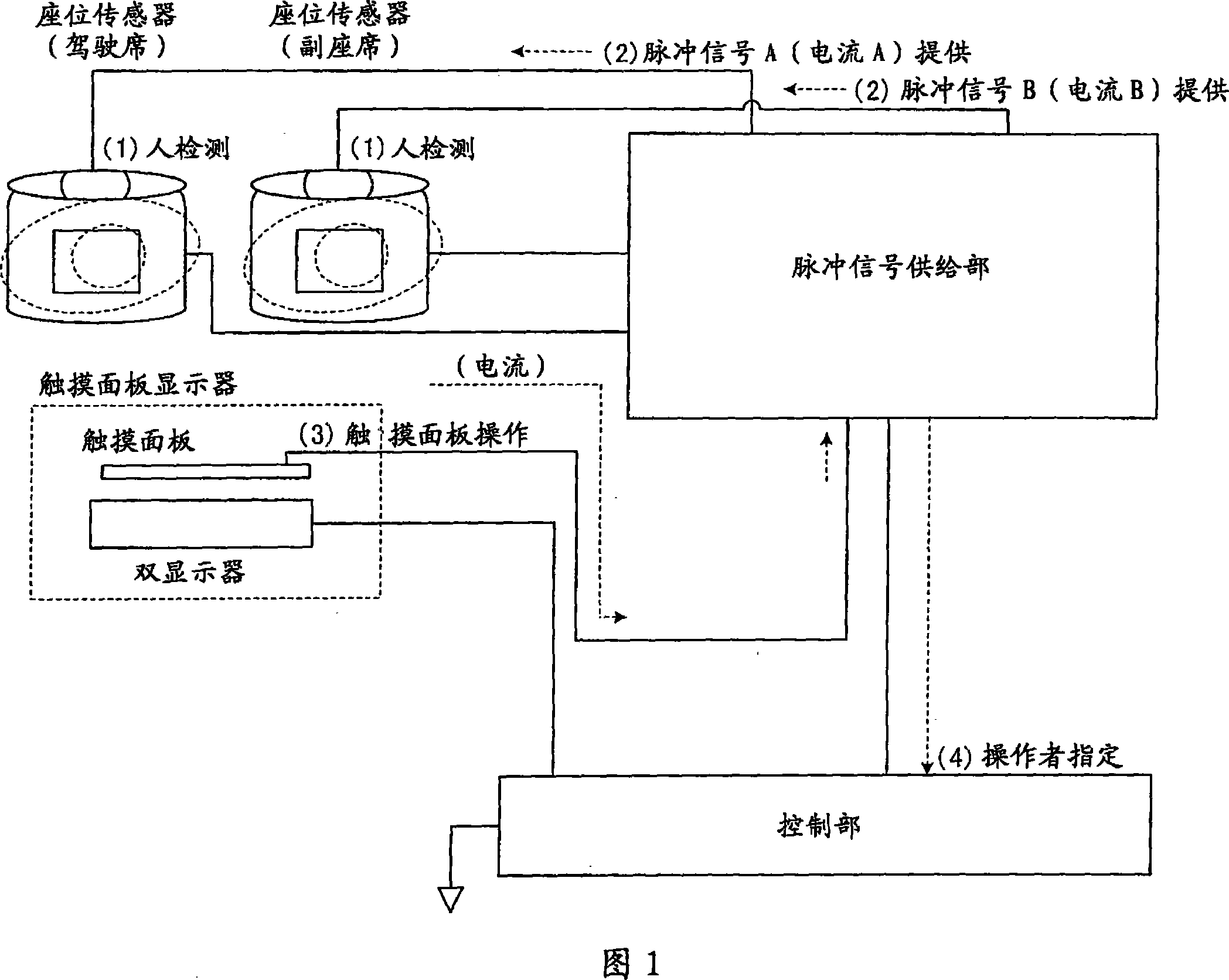
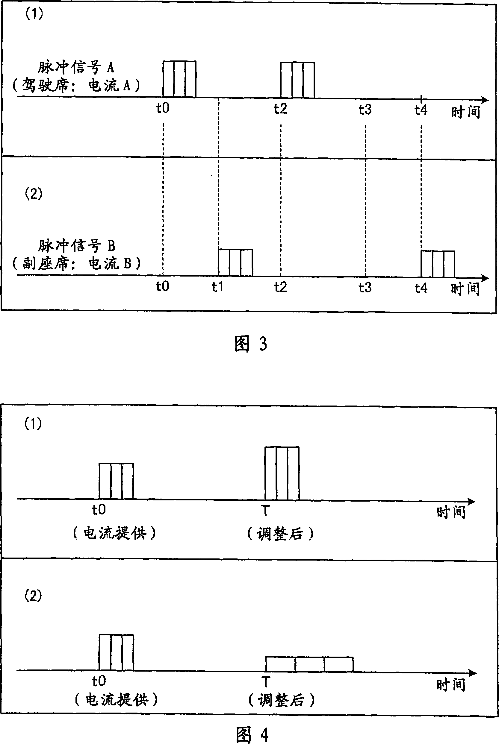
[0084] First, main terms used in this embodiment will be described. The so-called "vehicle system" used in this embodiment (corresponding to "display system", "operator designation method", and "vehicle display system" described in the scope of claims) is a computer such as a car navigation system installed in a vehicle. The system, specifically, displays car navigation and television (TV) and the like on a liquid crystal monitor and the like, and accepts various operations through a touch panel and a remote controller and the like. In such an "in-vehicle system" such as a car navigation system, either the car navigation or the TV is displayed on the liquid crystal monitor, and the setting of the destination or switching of the display format is accepted from the touch panel of the liquid crystal monitor during the car navigation. And perform, in addition, perform channel switching, volume adjustment, etc. while on TV. In addition, in the case ...
Embodiment 2
[0132] However, in Embodiment 1, the case where the pulse signal (current) supplied to the operator is detected by the touch panel has been described, but the present invention is not limited thereto, and detection by a hard switch is also possible.
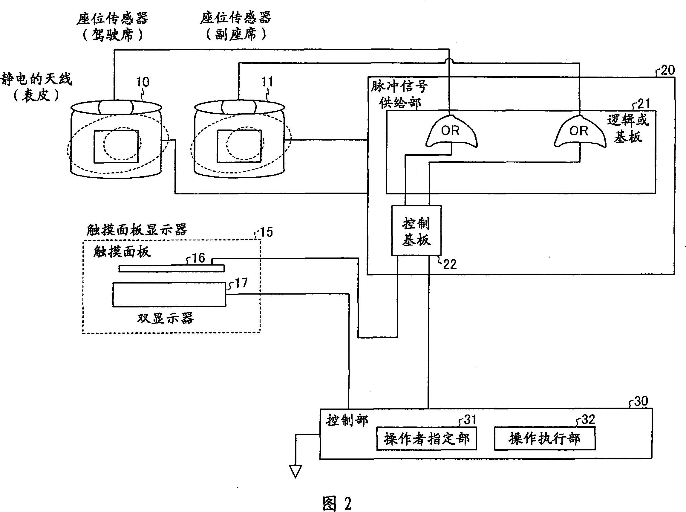
[0133] Therefore, in Example 2, the case where the pulse signal (current) supplied to an operator is detected by a hard switch is demonstrated using FIG.7 and FIG.8. First, the configuration of the in-vehicle system of the second embodiment will be described using FIG. 7 . In addition, FIG. 7 is a diagram showing the configuration of the in-vehicle system of the second embodiment.
[0134] [Configuration of Vehicle System (Embodiment 2)]
[0135]As shown in Figure 7, like embodiment 1, the vehicle-mounted system of embodiment 2 comprises: the seat sensor that is equipped on driver's seat and passenger seat; Provide the logic of pulse signal (current) or substrate, control substrate; Carry out various control The control unit; t...
Embodiment 3
[0171] However, in Embodiments 1 and 2, when the operator operates an input unit such as a touch panel or a hard switch, the case where a pulse signal is detected by the input unit and designated by the operator is described, the present invention does not Limiting to this, it is also possible to perform multiple samplings through the input unit, and specify by the operator based on the sampling results.
[0172] Therefore, in Embodiment 3, using FIGS. 11 to 13, when the operator operates the input unit, the pulse signal provided to the operator is sampled multiple times through the input unit, and the sampled pulse signal satisfies the prescribed The condition will be described for the case where the requirement is specified by the operator. In addition, since the configuration is the same as that of Embodiment 1 or Embodiment 2, description thereof will be omitted.
[0173] For example, in the vehicle-mounted system of the third embodiment, when the operator operates the in...
PUM
 Abstract
Description
Claims
Application Information