Centrifugal device comprising improved process analysis technology

A centrifuge and hollow technology, applied in the field of centrifuges, can solve the problems of hindering the washing fluid from washing the filter cake and cannot be determined, and achieve the effect of improving product quality

Inactive Publication Date: 2008-06-11
FIMA MASCHENBAU GMBH
View PDF0 Cites 2 Cited by
  • Summary
  • Abstract
  • Description
  • Claims
  • Application Information

AI Technical Summary

Problems solved by technology

In centrifuges up to now, this point of time was practically impossible to determine, since it simply waited until no more liquid phase escaped from the interior
However, when the liquid phase is completely drained, the problem arises that air bubbles are formed within the filter cake w

Method used


Image

  • Centrifugal device comprising improved process analysis technology
  • Centrifugal device comprising improved process analysis technology
  • Centrifugal device comprising improved process analysis technology

Examples


Embodiment Construction

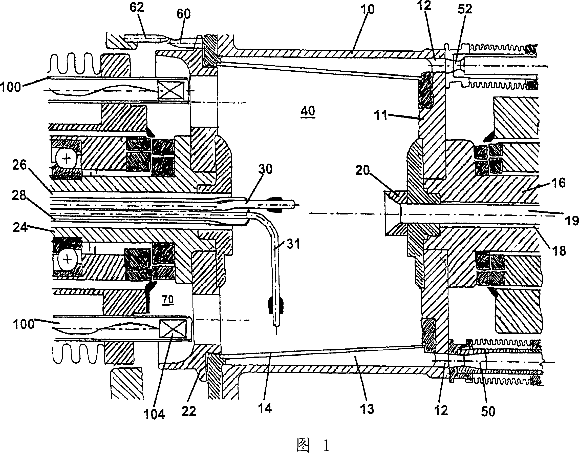
[0069] FIG. 1 shows the working chamber 40 and the filter 14 surrounding it. Filter 14 is a metal filter made of rigid material and has the shape of a cone. A drum 10 is disposed around the filter and includes holes 12 in the bottom of the drum. An annular space 13 is formed between the filter 14 and the drum 10 . One end of the working chamber 40 is formed by the bottom of the drum 10 , which is supported on the drive shaft 16 . The drive shaft 16 is hollow and has a drive shaft channel 18 therein, which serves as a filling channel for injecting a suspension. The funnel-shaped member 20 is connected to the drive shaft channel 18 . The baffle shaft 24 is located opposite the drive shaft 16 and the baffle 22 is supported on the baffle shaft. The flap shaft 24 is hollow and has a PAT channel 26 in it. In the PAT channel 26 a sleeve 28 in which three tubes 30 , 31 , 32 are housed extends. Two of these three tubes 30 , 31 , 32 are visible in FIG. 1 .

[0070] When injecting...


PUM


Abstract

The invention relates to a centrifugal device comprising improved process analysis technology (PAT), to a method for measuring the moisture content of a suspension in a centrifugal drum and to a method for sampling from a centrifugal device. According to the invention, the centrifugal device is equipped with: a drive shaft (16); a drum (10) that is connected to the drive shaft; a filter (14) that is located inside the drum (10) and that surrounds a working chamber (40); a baffle plate (22) that forms a front face of the working chamber (40) and that is mounted on a baffle plate shaft (24), the baffle plate (22) and the drum (10) being axially displaceable; a filler element (19) for filling a working chamber (40) with a suspension; and a centrifugal housing that surrounds the drum (10) and the filter (14). In addition, various process analysis devices are provided, in particular tubes (30, 31) comprising monitoring and measuring units that are inserted into the working chamber (40) and windows (102) comprising associated channels (100) that are configured in the baffle plate (22).

Description

technical field [0001] The present invention relates to an improved Process Analytical Technology (PAT) centrifuge, a method for measuring the moisture content of a suspension in a centrifuge bowl and a method for extracting a sample from the centrifuge. The term "centrifuge" when referring to the present invention is understood to mean a centrifuge of any embodiment. Within the scope of the present invention, centrifuges with an integrated drying function, so-called centrifugal dryers, are targeted in particular. However, the invention and the technical features disclosed within it can also be used for centrifuges without an integrated dryer and for all other centrifuge types. That is, the term centrifuge should be understood as not being limited to a certain type of centrifuge. Background technique [0002] Centrifuges are known for a wide range of applications in industry. Especially in the pharmaceutical industry centrifuges play an important role when producing pharm...

Claims


Application Information

Patent Timeline
IPC IPC(8): B04B3/00B04B9/02B04B11/05B04B11/06B04B11/08B04B13/00B04B15/06
CPCB04B9/02B04B11/06B04B3/00B04B11/05B04B13/00B04B11/082B04B15/06
Inventor 乔基姆·施密德
Owner FIMA MASCHENBAU GMBH
Why Eureka
Try Eureka