Clip ring embedded jig

A snap ring and fixture technology, applied in the direction of manufacturing tools, metal processing, metal processing equipment, etc., to achieve the effect of stable clamping

Active Publication Date: 2008-06-18
AISIN AW CO LTD
View PDF1 Cites 7 Cited by
  • Summary
  • Abstract
  • Description
  • Claims
  • Application Information

AI Technical Summary

Problems solved by technology

As a result, the entire circumference of the snap ring is expanded in diameter and cannot be fitted into the snap ring groove, resulting in poor fitting of the snap ring in a state where only the two ends c

Method used


Image

  • Clip ring embedded jig
  • Clip ring embedded jig
  • Clip ring embedded jig

Examples


Embodiment 1

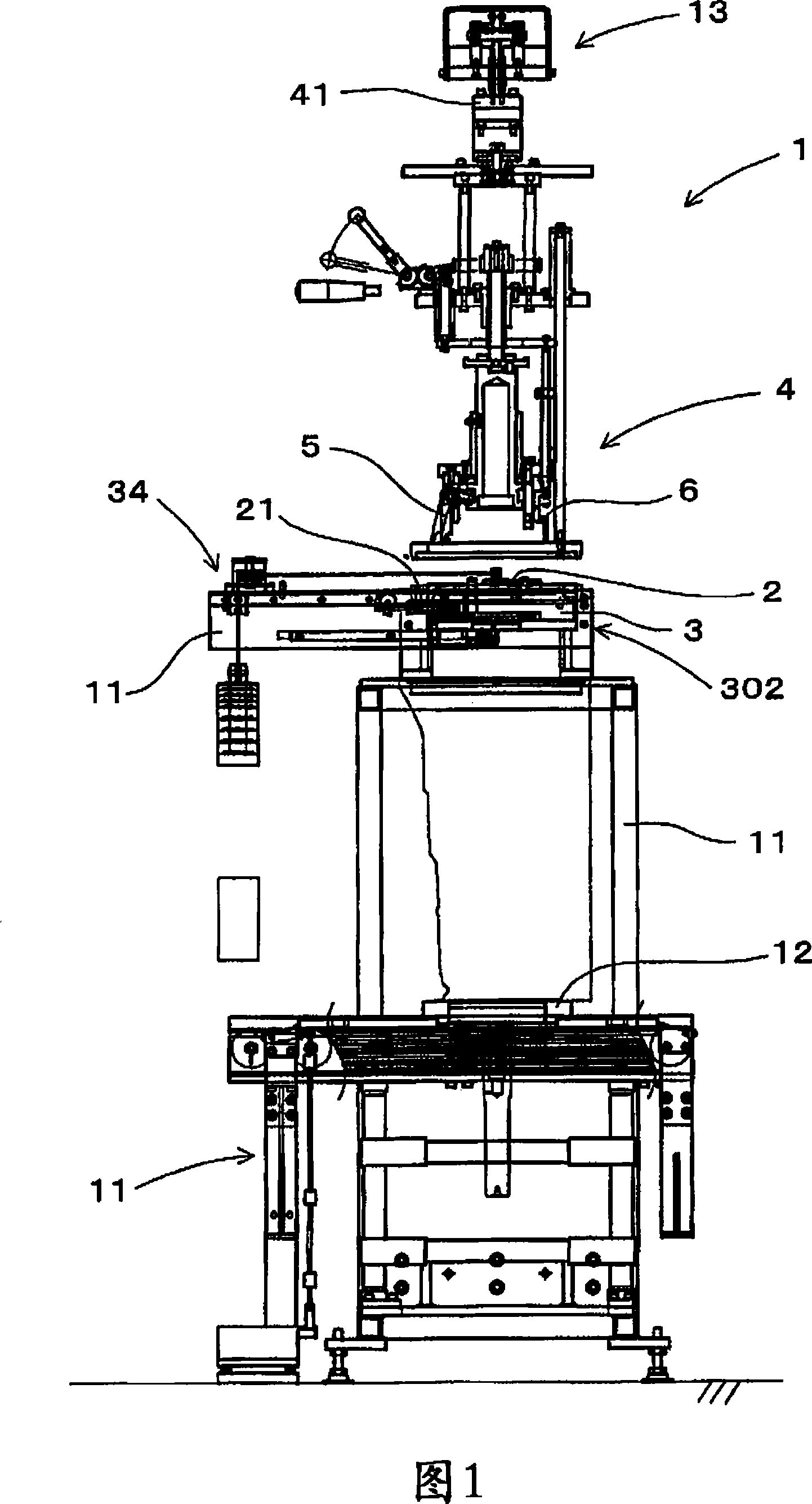
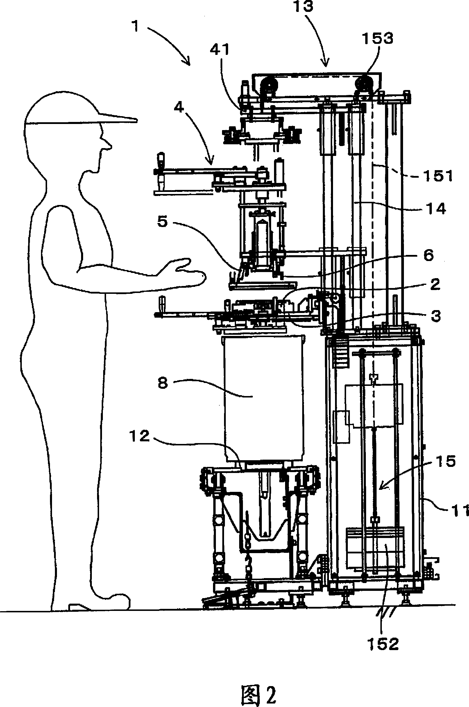
[0069] Next, the embodiment related to the jig for judging the front and back of the snap ring will be described in detail in conjunction with FIGS. 1 to 18 and 29 .

[0070] As shown in Fig. 1 and Fig. 8 to Fig. 12, the snap ring front and back judging jig 2 of this example is a jig for judging the front and back of the snap ring 9 when the snap ring 9 is handed over to the snap ring inserting jig 4. In addition, the snap ring fitting jig 4 is also a jig for fitting the snap ring 9 into the component to be assembled 8 .

[0071] As shown in Fig. 4 and Fig. 5, the snap ring 9 of this example has a C-shape with a notch 91 on a part of its circumference, the end surface 901 on one side in the axial direction is a vertical surface, and the end surface 901 on the other side in the axial direction is vertical. 902 has a sloped portion 92 . The slope portion 92 is formed to incline so that the thickness of the snap ring 9 decreases radially outward. In addition, at both end portio...

Embodiment 2

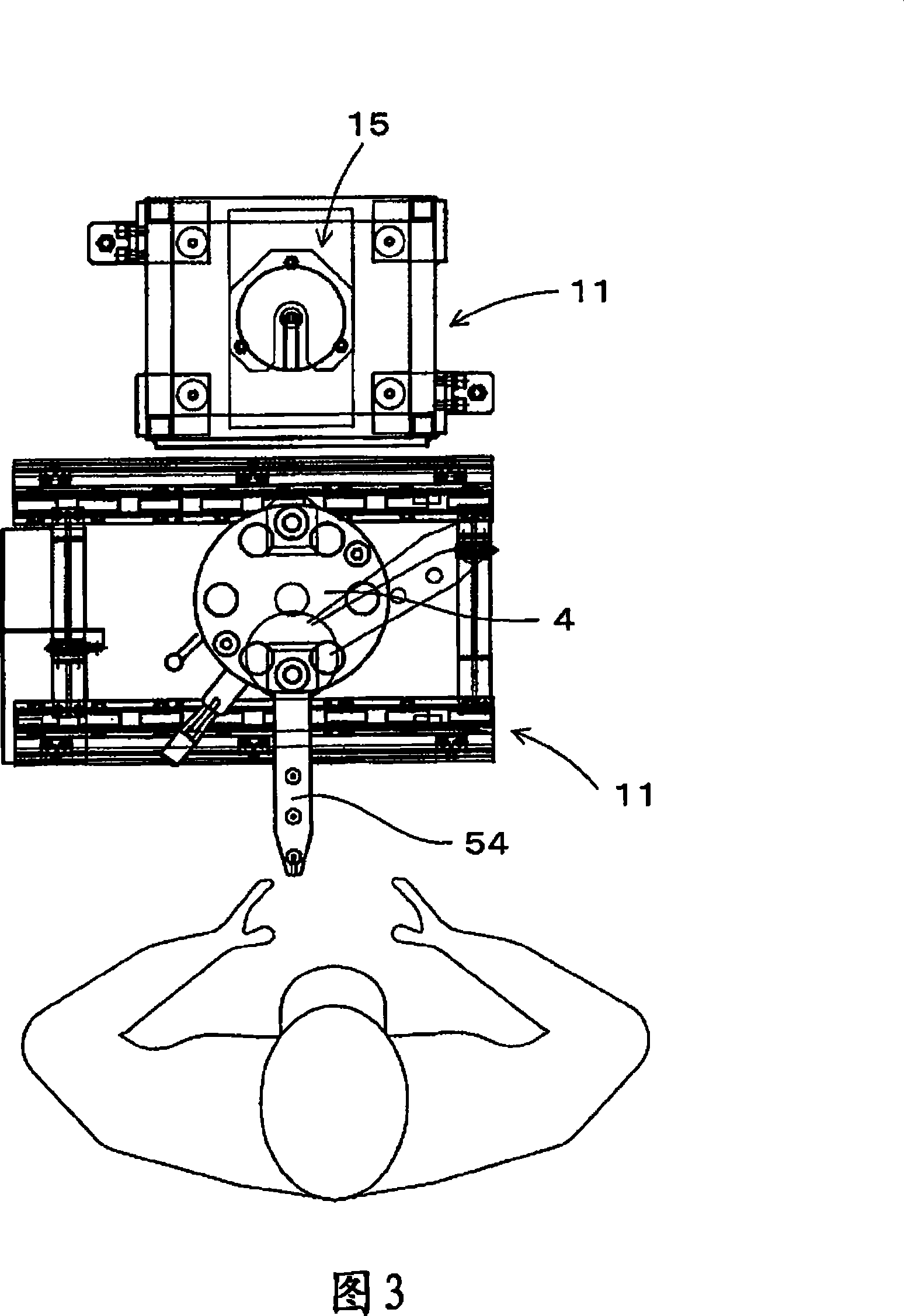
[0105] In this example, the above-mentioned snap ring fitting jig 4 will be described with reference to FIGS. 19 to 29 in particular.

[0106] As shown in Fig. 1 and Fig. 19 to Fig. 22, the snap ring fitting fixture 4 of this example is used to be inserted into the ring groove 82 formed in the circumferential direction in the assembling hole 81 of the assembled part 8, and has a The notch 91 is a clamp for the C-shaped snap ring 9 . In the assembly hole 81 of the component to be assembled 8 of this example, along the depth direction perpendicular to the peripheral direction of the assembly hole 81 , a plurality of depth direction grooves 83 in the circumferential direction of the assembly hole 81 are formed.

[0107] As shown in FIGS. 24 and 28 , the snap ring inserting jig 4 has a chuck portion 5 for clamping the outer periphery of the snap ring 9 and a push rod portion for pushing out the snap ring 9 clamped by the chuck portion 5 . 6. The chuck part 5 has a plurality of c...


PUM


Abstract

The present invention provides a snap ring fitting jig capable of stably fitting a snap ring into a ring groove in a component to be assembled. The snap ring embedding jig (4) includes a chuck part (5) having a plurality of chuck claws (521) and a push rod part (6). In the push-out front end surface (611) of the push-out snap ring (9) of the push rod part (6), the part (611A) that abuts against the middle part on the side opposite to the above-mentioned notch of the snap ring (9) , formed as the most prominent. Insert the snap ring into the jig (4), make the positions of the front end surfaces of the plurality of chuck claws (521) holding the snap ring (9) coincide with the positions of the opening side end surfaces (822) of the ring groove (82), and use the push rod part to For the ejection front end face (611) in (6), the snap ring (9) is ejected from the middle part earlier.

Description

technical field [0001] The present invention relates to a snap ring fitting jig for fitting a snap ring into a ring groove in a component to be assembled. Background technique [0002] In functional components such as automatic transmissions, a C-shaped snap ring having a notch is used to prevent axial misalignment of components disposed in a housing. [0003] In addition, when fitting the snap ring into the ring groove formed in the housing, for example, a snap ring assembly device disclosed in Patent Document 1 is used. This snap ring assembly device is configured to swingably hold a plurality of swing arms arranged radially with respect to a base, and to open and close the plurality of swing arms by a control member by operating an operation part by an operator. In this snap ring assembly device, the snap ring is elastically reduced in diameter and held by holding claws of a plurality of swing arms. Then, after moving the plurality of swing arms into the installed part,...

Claims


Application Information

Patent Timeline
IPC IPC(8): B23P19/02
Inventor 谷口孝男近藤展充桥本邦之冨田武沟口健治
Owner AISIN AW CO LTD
Why Eureka
Try Eureka