
Vehicle having its operating conditions regulated by fuel consumption

A technology for motor vehicles and fuel consumption, which is applied to the layout of power plant control mechanisms, electrical controls, control devices, etc., and can solve problems such as the inability to take fuel consumption into account

Inactive Publication Date: 2008-06-18
克里斯托瓦尔·古茨曼
View PDF0 Cites 6 Cited by
  • Summary
  • Abstract
  • Description
  • Claims
  • Application Information

AI Technical Summary

Problems solved by technology

The disadvantage of using a speed control is that it does not take into account the dependence of the fuel consumption altitude on (for example) the terrain of the route

Method used


Image

  • Vehicle having its operating conditions regulated by fuel consumption

Examples


Embodiment Construction

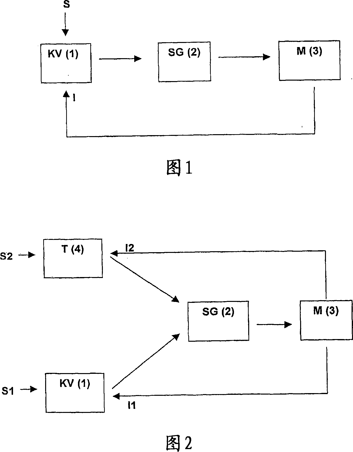
[0016] The control loop shown in the first diagram (Fig. 1) consists of three measuring elements. The first measuring element is fuel consumption regulator 1. The setpoint value for the fuel consumption is set here and the measured actual value is available. The control variables determined here act on the actuator 2 for adjusting the engine boost rate 3 . At the same time, the actual fuel consumption value is measured at certain sampling times and sent from the engine 3 to the controller 1 . The fuel consumption regulator compares the determined actual value with the setpoint value and changes the engine power by intervening 1 actuator 2 so that the actual value is equal to the set setpoint value. The determined rotational speed is then set to the engine 3 via the actuator 2 . The engine 3 runs at a set speed, and at the same time continues to measure the actual fuel consumption value at a certain sampling time, and sends it to the fuel consumption regulator 1 . The proce...


PUM


Abstract

The invention concerns a motor vehicle equipped with an instrument which captures the real fuel consumption value, a nominal consumption value being defined and the captured real value being used to regulate the power of the engine.

Description

Background technique [0001] It is known in modern motor vehicles (cars, trucks) to detect and display the instantaneous fuel consumption during driving, which is done analogously or digitally. The level of fuel consumption depends not only on the engine power of the vehicle, but also on personal driving style and road conditions. If the vehicle speed is high, brakes and accelerates continuously in urban traffic, fuel consumption will rise sharply. These display readouts make it possible for the driver to control fuel consumption and adapt it accordingly to his driving style in order to reduce fuel consumption. Of course, constant attention to the display readings is required to keep fuel consumption under control by manipulating the accelerator pedal or shifting into a more appropriate gear. [0002] Furthermore, it is also known in the state of the art to install electronic regulators in vehicles to control the vehicle speed. These speed regulators are called speed control...

Claims


Application Information

Patent Timeline
Patent Type & Authority Applications(China)
IPC IPC(8): F02D41/30F02D35/00B60K26/04
CPCF02D2200/701F02D2200/0614B60W2550/141F02D41/14F02D2200/0625B60W30/143Y02T10/52B60W2550/402Y02T10/84B60W2556/50B60W2552/05Y02T10/40F02D41/30F02D35/00B60K26/04
Inventor 克里斯托瓦尔·古茨曼
Owner 克里斯托瓦尔·古茨曼
Learn More