Lubricating device of rolling bearing

A technology of rolling bearing and lubricating device, applied in rolling contact bearing, rotating bearing, bearing, etc., can solve the problems of increased power loss and increased stirring resistance of cooling oil, and achieve the effect of reducing stirring resistance and good sealing.

Inactive Publication Date: 2008-06-18
NTN CORP
View PDF1 Cites 9 Cited by
  • Summary
  • Abstract
  • Description
  • Claims
  • Application Information

AI Technical Summary

Problems solved by technology

However, in a rolling bearing that supports a rotating shaft that rotates at a high speed of 10,000 revolutions per minute or more, such as the main shaft of a machine tool, when the amount of cooling oil flowing into the bearing increases, cooling will be brought along with the high-speed rotation of the rolling bearing. The stirring resistance of oil increases, so there is a problem of increased power loss

Method used


Image

  • Lubricating device of rolling bearing
  • Lubricating device of rolling bearing
  • Lubricating device of rolling bearing

Examples


Embodiment

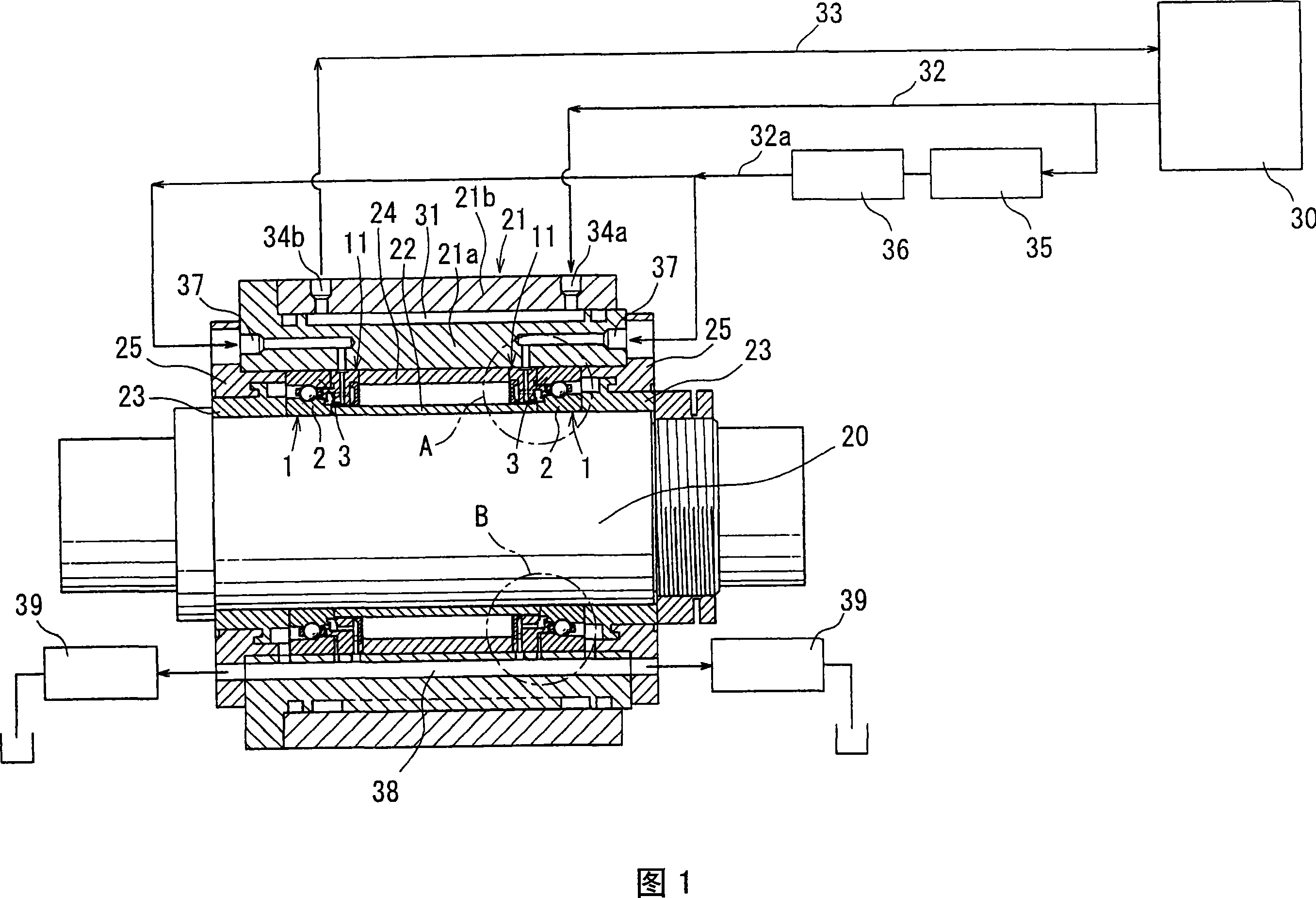
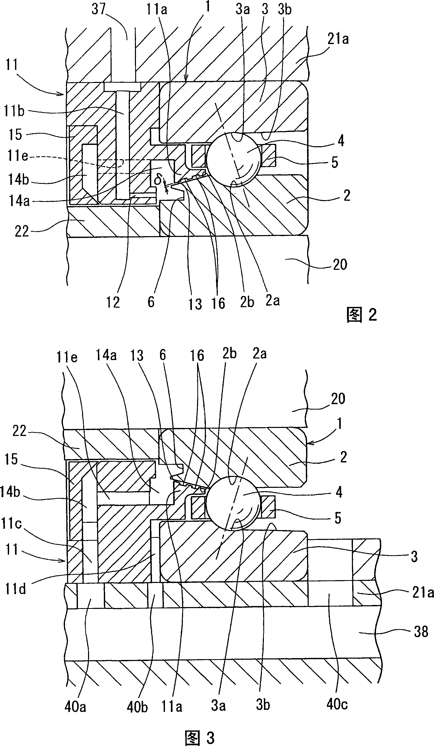
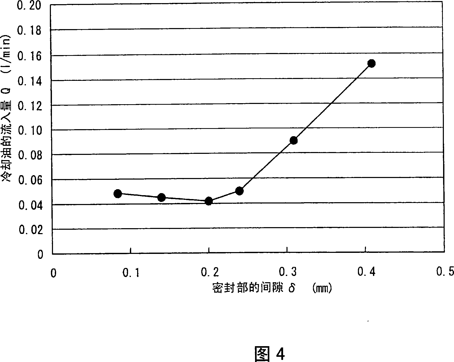
[0069] The gap δ of the sealing portion 13 as shown in FIG. 2 was changed, and the inflow amount Q of the cooling oil sprayed from the nozzle 12 into the inside of the bearing from the sealing portion 13 as lubricating oil was measured. The diameter of the main shaft 20 (inner diameter of the angular contact ball bearing 1 ) was set to 70 mm, the rotational speed thereof was set to 30000 rpm, and the discharge rate of the cooling oil from the nozzle 12 was set to 0.6 liter / minute.

[0070] FIG. 4 shows the measurement results of the inflow amount Q of the above-mentioned cooling oil. From the measurement results, it can be seen that the inflow amount Q of the cooling oil tends to become a horizontal line because the amount is small when the gap is 0.2 mm or less, and it increases rapidly when the gap exceeds 0.2 mm. Therefore, by setting the gap δ of the seal part to 0.2mm or less, the inflow quantity Q of the cooling oil flowing into the bearing can be stably controlled to a ...


PUM


Abstract

A lubricating device of a rolling bearing with an inner ring cooling function capable of reducing a coolant agitating resistance due to the high-speed rotation of the rolling bearing. A coolant introducing member (11) in which a nozzle (12) discharging a coolant to a circular groove (6) at the end face of the inner ring (2) is formed is disposed on the rear face side of an angular ball bearing (1), and a seal part (13) facing the tapered surface (2b) of the angular ball bearing (1) through a clearance is formed at the extension part (11a) of the coolant introducing member (11). The inflow amount of the coolant from the seal part (13) into the bearing is suppressed by setting the clearance d at the seal part (13) to 0.2 mm or less so that the coolant agitating resistance due to the high-speed rotation of the angular ball bearing (1) can be reduced.

Description

technical field [0001] The present invention relates to a lubrication device for a rolling bearing having a cooling function for an inner ring. Background technique [0002] In a rolling bearing that supports a rotating shaft that rotates at high speed, such as a main shaft of a machine tool, the temperature of the inner ring is higher than that of the outer ring due to machining loads or the like. Therefore, the preload of the bearing becomes too large due to the thermal expansion difference between the inner ring and the outer ring due to the temperature difference, and there is a problem that the life of the bearing is shortened. [0003] To solve this problem, there is a lubricating device for rolling bearings, which sprays cooling oil supplied from a cooling oil supply device from one end in the axial direction of the rolling bearing to the inner ring of the rotating ring, and is provided with the inner ring from which the cooling oil is sprayed. The outer diameter sur...

Claims


Application Information

Patent Timeline
Patent Type & Authority Applications(China)
IPC IPC(8): F16C33/66
CPCF16C19/548F16N2210/14F16C33/6674F16C33/667F16C35/12
Inventor 笹部光男森正继
Owner NTN CORP
Why Eureka
Try Eureka