Hybrid drive apparatus

a hybrid drive and drive technology, applied in the direction of mechanical actuated clutches, gearing details, transportation and packaging, etc., can solve the problems of increased drag torque, reduce the stirring resistance of oil, and effectively cool the friction engagement devi

Inactive Publication Date: 2012-08-30
AISIN AW CO LTD
View PDF5 Cites 5 Cited by
  • Summary
  • Abstract
  • Description
  • Claims
  • Application Information

AI Technical Summary

Benefits of technology

[0010]Thus, the filling state of the case member with the oil is switched by the communication mechanism. Accordingly, in the case where the friction engagement device generates a large amount of heat, the case member is filled with the oil to ensure the capability of cooling the friction engagement device. Moreover, in the case where the vehicle runs with the friction engagement device being disengaged, such as during EV running, the oil is discharged from the case member to reduce the stirring resistance of the oil generated by the friction plates, whereby the drag torque of the hybrid drive apparatus can be reduced.
[0011]Moreover, since the second supply oil amount that is supplied to the internal space of the case member when the friction engagement device starts to slip is made larger than the first supply oil amount that is supplied to the internal space of the case member when the friction engagement device is disengaged, a large amount of oil can be supplied to the internal space of the case member in the slipping state in which the friction plates slip and rotate and the friction engagement device generates heat. Accordingly, the friction engagement device can be effectively cooled. Even if the inside of the case member is empty when the friction engagement device starts to slip, the oil is supplied to the internal space of the case member by the second supply oil amount larger than the first supply oil amount, and thus the internal space of the case member can be rapidly filled with the oil.

Problems solved by technology

However, such a hybrid car has the following problem.
If the engine is connected to the drive system even during EV running during which the engine is not used, drag torque is increased due to dragging of the engine.
However, such a clutch capable of allowing and interrupting power transmission from the engine may transmit power while causing the clutch to slip, such as when the vehicle is started by the engine, Thus, in hybrid drive apparatuses described in Japanese Patent Application Publication No.

Method used


Image

  • Hybrid drive apparatus
  • Hybrid drive apparatus
  • Hybrid drive apparatus

Examples


first embodiment

[0023][Schematic Configuration of Hybrid Drive Apparatus]

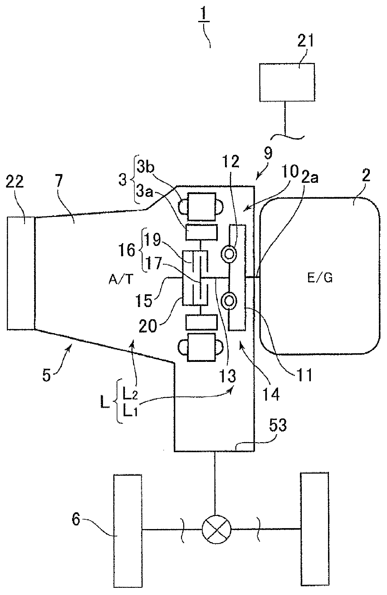
[0024]As shown in FIG. 1, a hybrid car 1 has, as driving sources, a rotating electrical machine (a motor generator) 3 in addition to an engine 2, and a hybrid drive apparatus 5 forming a power train of the hybrid car 1 is configured to include a transmission device 7 provided on a transmission path L between the engine 2 and wheels 6, and an input portion 9 placed between the transmission device 7 and the engine 2 to receive power from the engine 2.

[0025]The input portion 9 is formed by providing with the rotating electrical machine 3 a power transmission device 10 that transmits power between the engine 2 and the transmission device 7. This power transmission device 10 is formed by a connection portion 14 having a damper 12 that is connected to a crankshaft 2a of the engine 2 via a drive plate 11 and a connection shaft 13 on which the damper 12 is spline fitted, and a clutch (a friction engagement device) 16 that allows and i...

second embodiment

[0106]A second embodiment of the present invention will be described below. Note that the second embodiment is configured so that the oil amount to be supplied to the internal space S of the clutch housing 20 can be changed to three stages, as opposed to the first embodiment. Description of the configurations similar to those of the first embodiment is omitted, and such configurations are denoted with like reference characters.

[0107]As shown in FIG. 5, the circulating-oil amount adjustment portion (the oil amount adjustment portion) 68 is formed by a modulator valve 80 that regulates an original pressure received from the oil pump device 30 to a predetermined pressure, and a switch valve 81 to which the certain oil pressure regulated by the modulator valve 80 is input, and which switches the oil amount to be supplied to the internal space S of the clutch housing 20.

[0108]As show in FIG. 6, the switch valve 81 is configured to have a spool 81p, a spring 81s that biases the spool 81p ...

third embodiment

[0123]A third embodiment of the present invention will be described below. The third embodiment is configured so that the switch valve 81 of the second embodiment is capable of being switched by a control linear solenoid valve 90, and description of configurations similar to those of the first and second embodiments is omitted, and such configurations are denoted with like reference numerals.

[0124]As shown in FIG. 7, the circulating-oil amount adjustment portion (the oil amount adjustment portion) 68 has, in addition to the modulator valve 80 and the switch valve 81, the control linear solenoid valve 90 that outputs a control pressure to the oil chamber 81e of the switch valve 81. The position of the spool 81p of the switch valve 81 is capable of being switched by controlling by the control portion 21 the control pressure to be output from the control linear solenoid valve 90.

[0125]Thus, as shown in FIGS. 8 and 9, the control linear solenoid valve 90 is switched to a non-output stat...


PUM


Abstract

A hybrid drive apparatus includes a case with first and second friction plates that can be soaked with oil. A communication mechanism allows or cuts off the communication between an internal space of the case and outside, and discharges the to the outside when the internal space communicates with the outside. A controller controls an engagement pressure to obtain a disengaged state in which the first and second friction plates are disengaged and a slipping state in which the first and second friction plates slip and rotate. An oil adjustment portion adjusts an oil amount supplied to the internal space, based on a control state of the friction engagement device, and adjusts the oil amount to a first amount when the friction engagement device is disengaged, and adjusts the oil amount to a second amount larger than the first amount when the friction engagement device starts to slip.

Description

INCORPORATION BY REFERENCE[0001]The disclosure of Japanese Patent Application No. 2011-043382 filed on Feb. 28, 2011 including the specification, drawings and abstract is incorporated herein by reference in its entirety.BACKGROUND OF THE INVENTION[0002]The present invention relates to hybrid drive apparatuses including a friction engagement device placed on a transmission path between an engine and wheels.[0003]1. Description of the Related Art[0004]In recent years, hybrid cars including a rotating electrical machine in addition to an engine as driving sources have been actively studied due to increasing environmental awareness. Since such a hybrid car has a rotating electrical machine as a driving source as described above, the hybrid car not only runs by the engine, but also regenerates kinetic energy of the vehicle by the rotating electrical machine, and runs only by the rotating electrical machine without using the engine (EV running), in order to improve energy efficiency.[0005...

Claims


Application Information

Patent Timeline
Patent Type & Authority Applications(United States)
IPC IPC(8): F16D13/72
CPCB60K6/48Y02T10/6221B60W20/00B60W30/186F16H57/0473B60W2710/023F16D25/123F16D48/02F16D48/066F16D2048/0209F16D2048/0233F16D2048/0281F16D2048/029F16D2500/1066F16D2500/30406F16D2500/70412F16D2500/70446B60W10/02Y02T10/62B60W20/40B60W10/023
Inventor NODA, KAZUYUKISUZUKI, KEIJI
Owner AISIN AW CO LTD
Why Eureka
Try Eureka