Method of designing both-plane aspherical progressive refractive power lens group and both-plane aspherical progressive refractive power lens group

A technology of refractive index and lens group, applied in glasses/protective glasses, glasses/goggles, optics, etc., can solve the problems of poor method efficiency and increased cost, and achieve the effect of wide field of view

Active Publication Date: 2008-06-18
HOYA CORP
View PDF6 Cites 11 Cited by
  • Summary
  • Abstract
  • Description
  • Claims
  • Application Information

AI Technical Summary

Problems solved by technology

The method in which two surfaces have to be machined after receivi...

Method used


Image

  • Method of designing both-plane aspherical progressive refractive power lens group and both-plane aspherical progressive refractive power lens group
  • Method of designing both-plane aspherical progressive refractive power lens group and both-plane aspherical progressive refractive power lens group
  • Method of designing both-plane aspherical progressive refractive power lens group and both-plane aspherical progressive refractive power lens group

Examples


example 1

[0095] Figure 21 is a graph showing the list of Surface Refractive Index, Hyperopia Power, and Addition Power for Examples 1-4 (described below) in Tables 1-4, respectively. Tables 1-4 in FIG. 21 correspond to Examples 1-4 described below and are listings of surface refractive index, hyperopic power, and add-on power. The meanings of the items appearing in Table 1-4 are as follows:

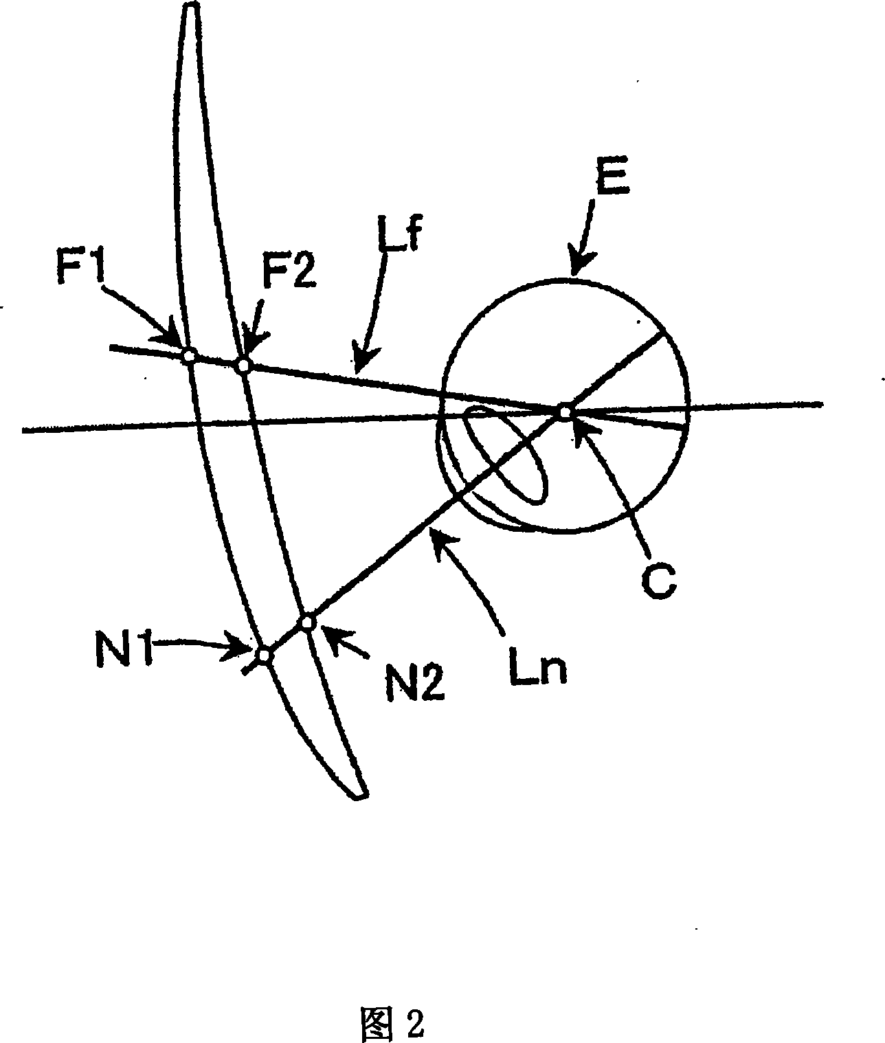
[0096] DVf1: the surface refractive index on the object side surface in the vertical direction at the farsighted power measurement position F1;

[0097] DHf1: the surface refraction index in the horizontal direction at the distance measurement position F1 on the object side surface;

[0098] DVn1: the surface refraction index on the vertical direction at the myopia power measurement position N1 place on the object side surface;

[0099] DHn: the surface refractive index in the horizontal direction at the myopia measurement position N1 on the object side surface;

[0100] DVf2: the surface refra...

example 1

[0119] (Example 1-a, Example 1-b, Example 1-c, Example 1-d)

[0120] Table 1 and Figures 5-8 correspond to Example 1-a, Example 1-b, Example 1-c, and Example 1-d, respectively. These examples use the same object-side surface to provide different degrees of addition. It is understood that although the values ​​of DVf1, DHf1, DVn1, and DHn1 in Table 1 are the same as each other, the ADD values ​​are also different. The same applies to Figs. 5-8. The surface glitch at N1 is completely eliminated by the surface glitch at N2. For the degrees of myopia at N1 and N2, due to the difference in average refractive index between N1 and N2, different additional degrees are given, such as +1.00, +2.00, +3.00, +3.50; meanwhile, for F1 and Hyperopia at F2, the average refractive index difference between F1 and F2 is both 0.00.

example 2-a, example 2-b、 example 2-c、 example 2-d

[0122] Table 2 and Figures 9-12 correspond to Example 2-a, Example 2-b, Example 2-c, Example 2-d, respectively. These examples use the same object-side surface to provide different degrees of addition. It is understood that although the values ​​of DVf1, DHf1, DVn1, and DHn1 in Table 2 are the same as each other, the ADD values ​​are also different. The same applies to Figs. 9-12. The surface glitch at N1 is completely eliminated by the surface glitch at N2. Similarly, for hyperopia, the average refractive index difference between F1 and F2 is -1.00; for myopia, since the average refractive index difference between N1 and N2 is different, different additional degrees are given, such as + 1.00, +2.00, +3.00 and +3.50.


PUM


Abstract

A double aspheric progressive refractive index lens group capable of reducing processing costs. In the double aspheric progressive index lens, the relationship: DHf+DHn<DVf+DVn and DHn<DVn or further the relationship: DVn−DVf>ADD/2 and DHn−DHf<ADD/2 is satisfied. DHf and DVf are respectively designated as the surface refractive index in the horizontal direction and the surface refractive index in the vertical direction at the farsighted power measurement position F1 on the first refraction surface as the object-side surface; DHn and DVn are respectively designated as The surface refractive index in the horizontal direction and the surface refractive index in the vertical direction at the myopia power measurement position N1 on the first refraction surface. The surface glare components at F1 and N1 of the first refractive surface are eliminated by the second refractive surface, the first and second refractive surfaces being combined to provide far vision power (Df) and add power (ADD) based on prescribed values. Therein, the same first refractive surface is used for at least two or more different addition degrees.

Description

technical field [0001] The present invention relates to a bi-aspherical type progressive-power lens used, for example, as a progressive-power lens for presbyopic spectacles constructed to have progressive refraction A power function, the progressive refractive index function is separately assigned to the first refractive surface of the object side surface and the second refractive surface of the eyeball side surface, so that the first surface and the second surface together provide far vision power (far vision power) and Addition power based on a specified value. Background technique [0002] In recent years, Patent Documents 1 to 5 disclose a design method of a double-aspheric type progressive-refractive-index lens, wherein the design method involves decomposing elements having a progressive refractive index into a convex surface side (object side) and a concave surface side (eye side). ). [0003] Specifically, Patent Documents 2-5 propose reducing glare by combining pro...

Claims


Application Information

Patent Timeline
IPC IPC(8): G02C7/06
CPCG02C2202/08G02C7/061G02C7/068
Inventor 木谷明畑中隆志菊池吉洋
Owner HOYA CORP
Why Eureka
Try Eureka