System, apparatus and method for active mirrors with blind spot detection

Inactive Publication Date: 2009-10-01
FORD GLOBAL TECH LLC
View PDF24 Cites 15 Cited by
  • Summary
  • Abstract
  • Description
  • Claims
  • Application Information

AI Technical Summary

Benefits of technology

[0014]In yet another embodiment, the method may include an operator's manual actuation of the mirror

Problems solved by technology
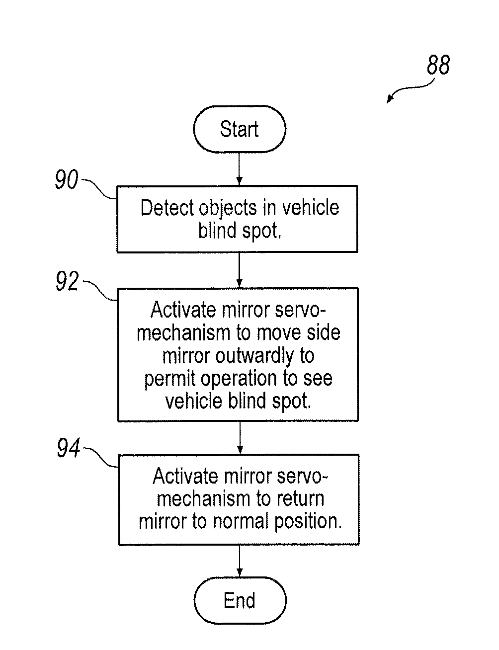
In automotive or other vehicle environments, interior and exterior rearview mirrors can leave blind spots in an operator's field of vision.
There has been some consideration that the visual indicator may be an annoyance or even a distraction to some vehicle operators.
Thus, customer acceptance of the feature may be less than desired as the annoyance of the warning alert, such as a light in the mirror, an audio or even a h

Method used


Image

  • System, apparatus and method for active mirrors with blind spot detection
  • System, apparatus and method for active mirrors with blind spot detection
  • System, apparatus and method for active mirrors with blind spot detection

Examples


Example

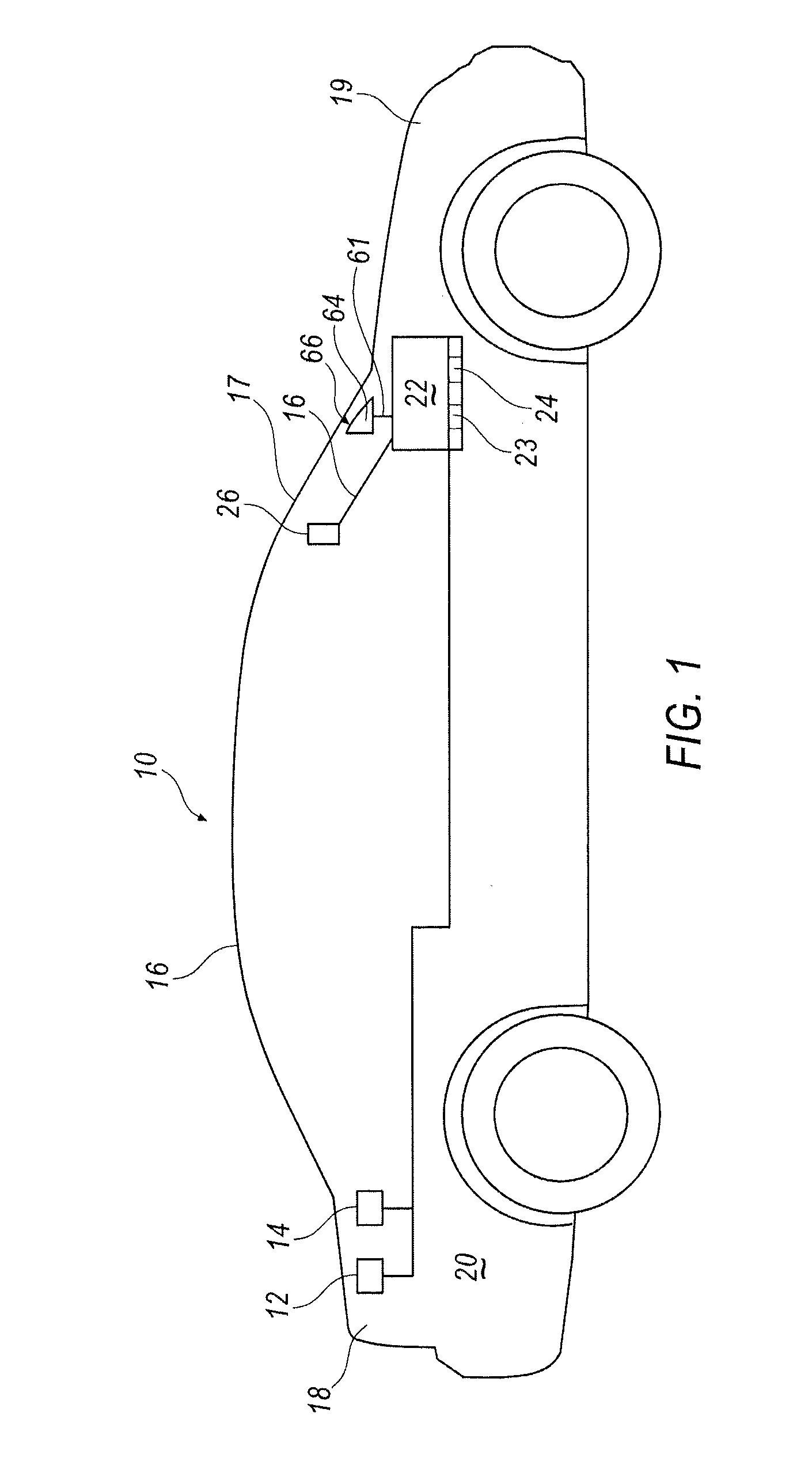
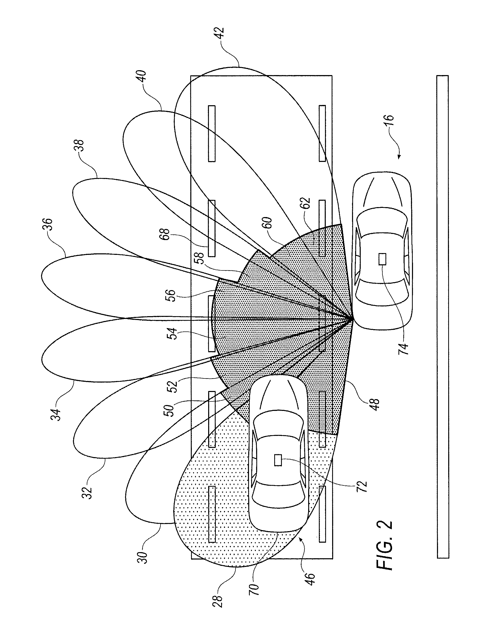
[0022]Turning now to the drawings wherein like numbers depict like structures, and particularly to FIG. 1, system 10 is comprised of at least two radar sensors 12, 14, which may be positioned on a host vehicle 16, such that it is in the rear 18 and sides 20 of the vehicle so that any blind spot is under surveillance. While one side of a vehicle is discussed, it is apparent to those skilled in the art that both sides of the vehicle are equipped with identical structures that mirror each other. While a radar based system is discussed it is apparent that a visual or motion detection system could also function as the blind spot detection system. The input from the radar sensors is transmitted to an electronic control module (ECU) 22 with memory 23. The ECU has a memory such as PROM, EPROM, EEPROM, Flash, or any other memory, and various tables are contained therein wherein maximum and minimum ranges are stored. In addition, the ECU may contain look up tables that contain various times f...


PUM


Abstract

A system, apparatus and method to automatically move a side mounted mirror on a vehicle from an inward position to an outward position in response to a signal from a detector indicative of an object outside an operator normal field of vision. The detector may be a blind spot detection system or a lane departure system, or any other system to detect vehicles in a blind spot. The system, apparatus and method further includes permitting an operator to manually actuate the movement of mirror on a vehicle to determine whether there are any objects in the operator's normal field of vision. The systems and method may optionally include hysteresis during mirror movement.

Description

TECHNICAL FIELD[0001]In automotive or other vehicle environments, interior and exterior rearview mirrors can leave blind spots in an operator's field of vision. Blind spot detection systems have been proposed and developed as at least partial solutions to this challenge. In some embodiments, blind spot detectors can utilize a visual indicator, usually in the sideview or rearview mirror itself, or in close proximity thereof, to alert an operator that a vehicle or other object is in the vehicle blind spot. There has been some consideration that the visual indicator may be an annoyance or even a distraction to some vehicle operators. Auditory alarms and haptic alarms indicating an object is in the blind spot may also be perceived by some as a distraction. Thus, customer acceptance of the feature may be less than desired as the annoyance of the warning alert, such as a light in the mirror, an audio or even a haptic alert may cause some customers not to opt for such a blind spot detectio...

Claims


Application Information

Patent Timeline
IPC IPC(8): G02B7/198
CPCB60R1/072B60R2300/301B60R1/081
Inventor SCHONDORF, STEVEN YELLINSCHONDORF, KRISTIN MARIE
Owner FORD GLOBAL TECH LLC
Why Eureka
Try Eureka