Measurement microscope device, image generating method, measurement microscope device operation program, and computer-readable recording medium

a technology of measurement microscope and operation program, which is applied in the field of measurement microscope device, image generating method, measurement microscope device operation program, and computer-readable recording medium, can solve the problems of restricted imageable visual field range, and difficult to make both favorable, so as to achieve wide visual field without deterioration in measurement accuracy

Active Publication Date: 2016-03-22
KEYENCE
View PDF0 Cites 14 Cited by
  • Summary
  • Abstract
  • Description
  • Claims
  • Application Information

AI Technical Summary

Benefits of technology

[0010]The present invention has been made for solving the conventional problems described above. An object of the present invention is to provide a measurement microscope device, an image generating method, a measurement microscope device operation program, and a computer-readable recording medium, which allow an image to be captured with a wide visual field without causing deterioration in measurement accuracy.
[0011]In order to achieve the above object, a measurement microscope device according to one embodiment of the invention may include: a first measurement light projecting unit configured to irradiate an object with first measurement light from a first direction, the unit being a measurement light projecting unit for projecting measurement light as predetermined pattern structured illumination to the object from an oblique direction; an observation illumination light source for generating illumination light when capturing an observation image; an imaging unit for acquiring measurement light projected by the first measurement light projecting unit and reflected by the object to capture a plurality of striped images, and using the observation illumination light source to capture an observation image having texture information; a height image acquiring unit for acquiring a height image having height information based on the plurality of striped images; a stage on which the object is placed; a display unit for displaying the height image or the observation image; a measurement unit for performing measurement on the height image displayed on the display unit; an image connecting unit configured to, by moving the stage and capturing a different region including a connection margin by the imaging unit, acquire a plurality of height images for connection and observation images for connection, and connect the obtained plurality of height images for connection and observation images for connection to generate a connected image; a measurement error region display unit configured to superimpose and display a measurement error region, where a result of measurement of the height is error, on an image of the object corresponding to each region to be connected by the image connecting unit; and a measurement-image imaging condition setting unit for adjusting an imaging condition for a striped image required for generation of the height image to reduce the measurement error region in a state where the measurement error region is displayed. With the above configuration, a plurality of images each having high accuracy but a narrow imageable visual field are captured while these images are connected, whereby it is possible to obtain an image with a wide visual field and high accuracy. In particular, by changing the imaging condition of the measurement image not used as the texture image rather than the observation image used as a texture image, it is possible to avoid a state where the appearance of the connected image changes significantly with respect to each area, while eliminating the measurement error region, so as to obtain a high quality connected image.

Problems solved by technology

In such a measurement device capable of capturing image data in the three-dimensional shape, an imageable visual field range is restricted by performance of an imaging element or the like.
It is desirable that a three-dimensional image is captured with a visual field as wide as possible for efficiently performing the measurement, but when a wide visual field is to be captured, resolution of the obtained image decreases to cause deterioration in measurement accuracy.
As described above, the visual field and the accuracy have a trade-off relation where, when one is taken as important, the other is neglected, and it has thus been difficult to make the both favorable in the past.
In this case, a large number of images need to be captured, and it thus takes a long time.
Hence there has been a problem of not being able to successfully perform measurement in a standard measurement mode.
However, when measurement is performed in a highest-class measurement mode, it blindly takes time.
As described above, there has been a problem in that the measurement time is difficult to reduce when images captured by the stripe projection method are to be connected.

Method used


Image

  • Measurement microscope device, image generating method, measurement microscope device operation program, and computer-readable recording medium
  • Measurement microscope device, image generating method, measurement microscope device operation program, and computer-readable recording medium
  • Measurement microscope device, image generating method, measurement microscope device operation program, and computer-readable recording medium

Examples


first embodiment

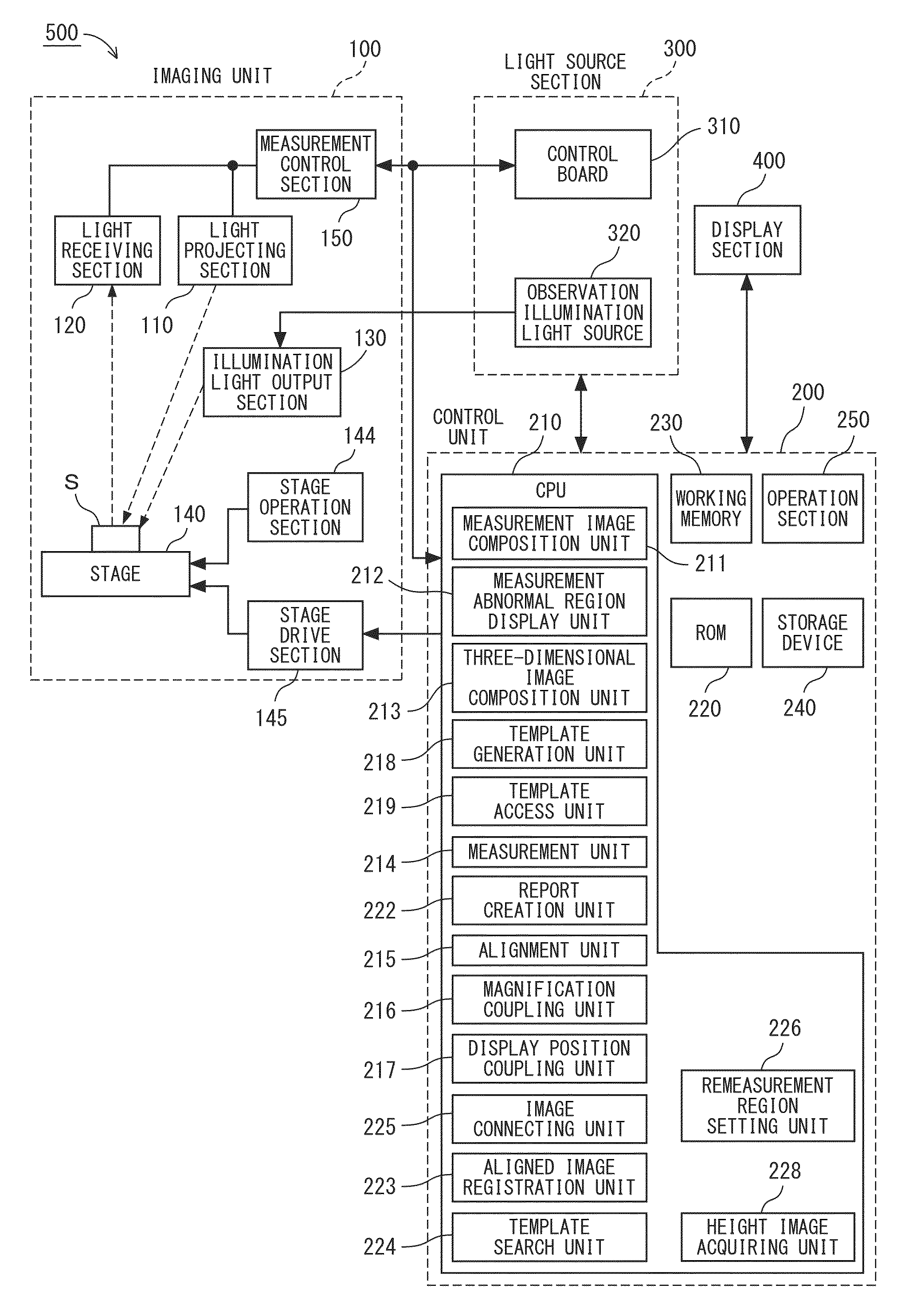
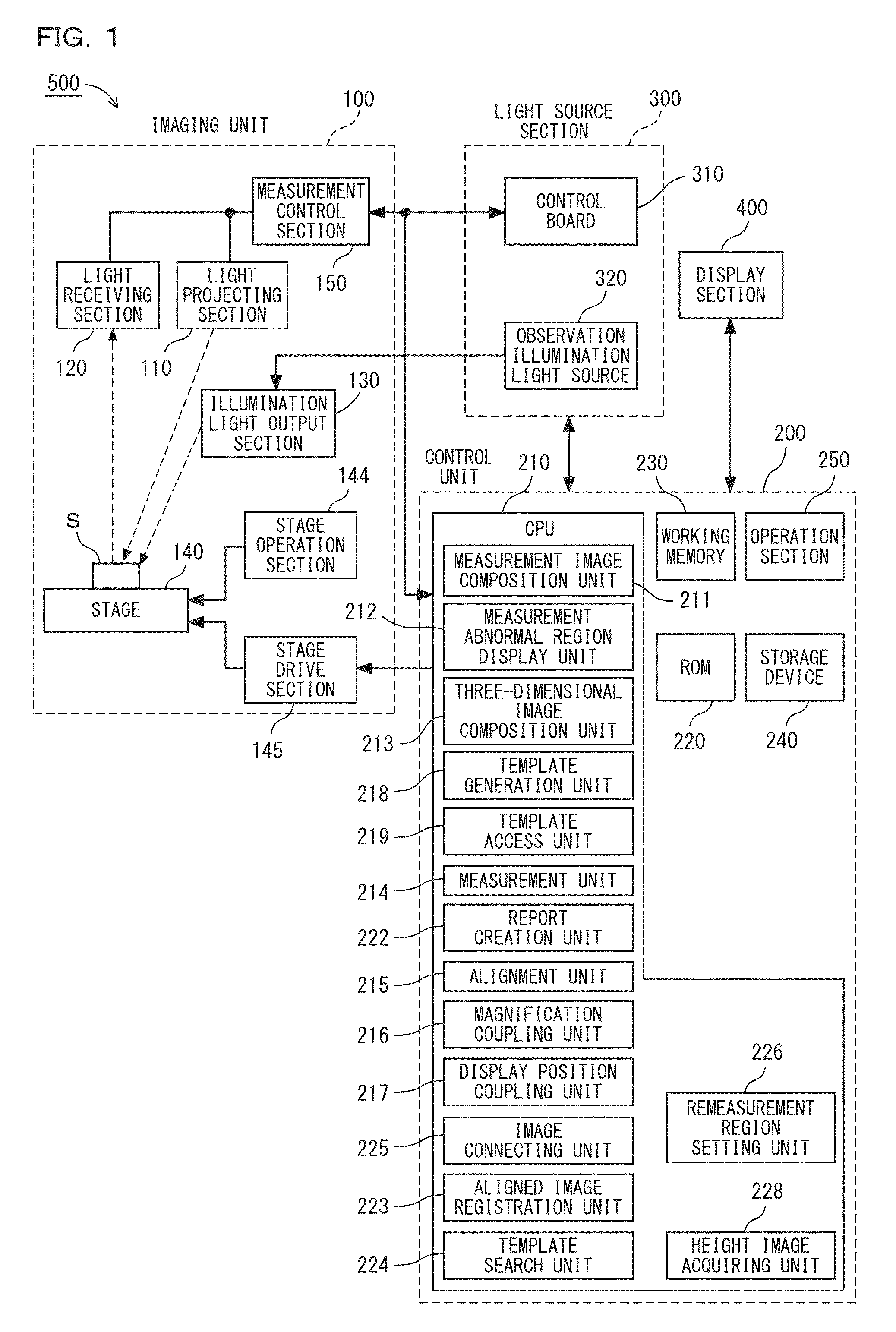
[0116]FIG. 1 is a block diagram showing a configuration of a measurement microscope device according to a first embodiment of the present invention. As shown in FIG. 1, a measurement microscope device 500 is provided with an imaging unit 100, a control unit 200, a light source section 300 and a display section 400.

(Imaging Unit 100)

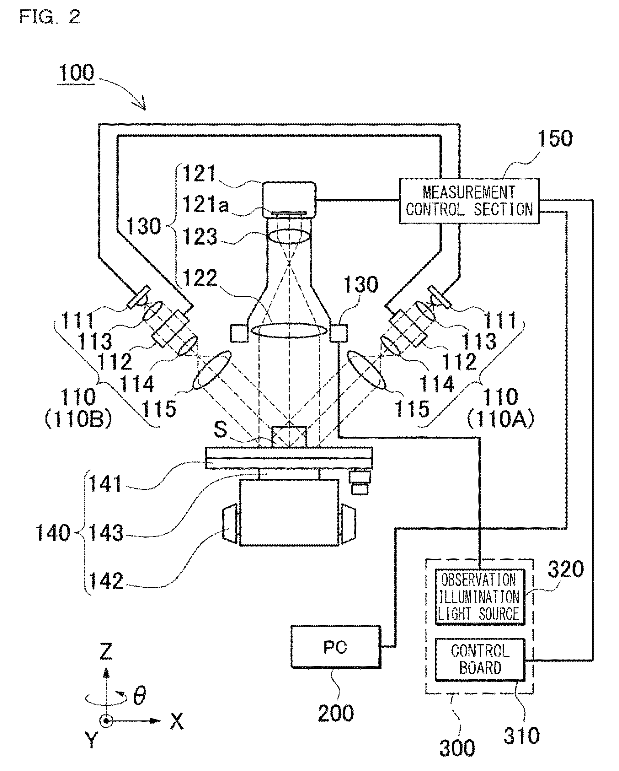
[0117]A configuration of the imaging unit 100 of the measurement microscope device 500 of FIG. 1 is shown in a block diagram of FIG. 2. The imaging unit 100 is, for example, a microscope and includes a light projecting section 110, a light receiving section 120, an illumination light output section 130, a stage 140 and a measurement control section 150. The light projecting section 110 includes a measurement light source 111, a pattern generating section 112, and a plurality of lenses 113, 114 and 115. The light receiving section 120 includes a camera 121 and a plurality of lenses 122 and 123. An object S is placed on the stage 140.

(Light Projecting Secti...


PUM


Abstract

An image with a wide visual field can be captured without causing deterioration in measurement accuracy. There are provided: a stage on which an object is placed; a display unit for displaying a height image or an observation image; a measurement unit for performing measurement on the height image; an image connecting unit configured to, by moving the stage and capturing a different region, acquire a plurality of height images, and connect the obtained plurality of height images and observation images to generate a connected image; a measurement error region display unit configured to superimpose and display a measurement error region, on an image of the object; and a measurement-image imaging condition setting unit for adjusting an imaging condition for a striped image required for generation of the height image to reduce the measurement error region.

Description

CROSS-REFERENCE TO RELATED APPLICATIONS[0001]The present application claims foreign priority based on Japanese Patent Application No. 2012-263871, filed Nov. 30, 2012, the contents of which is incorporated herein by reference.BACKGROUND OF THE INVENTION[0002]1. Field of the Invention[0003]The present invention relates to a measurement microscope device provided with a measurement function, an image generating method, an operation program for operating this measurement microscope device, and a computer-readable recording medium.[0004]2. Description of Related Art[0005]There has been developed a measurement device using triangulation as a measurement device for measuring an object. As shown in FIG. 84, such a device is previously set with an angle α between an optical axis of measurement light emitted from a light projecting section 110 and an optical axis of measurement light incident on a light receiving section 120 (an optical axis of the light receiving section 120). When an objec...

Claims


Application Information

Patent Timeline
Patent Type & Authority Patents(United States)
IPC IPC(8): H04N9/47G02B21/36G06K9/46G01B9/04G01B11/24H04N7/18G02B21/00G06K9/00G01B11/25G06K9/20G06V10/145
CPCG01B9/04G01B11/2531G02B21/0016G01B11/24G02B21/367G06K9/00134G06K9/00214G06K9/2036G06K9/4638G01B2210/52G06V20/693G06V20/653G06V10/145G06V10/457G06V20/66
Inventor TAKAHASHI, SHINYA
Owner KEYENCE
Why Eureka
Try Eureka