Sensitization structure for optical fiber grating sensor

A technology of optical fiber grating and sensitization structure, which is applied in the direction of transmitting sensing components, instruments, special recording/indicating devices, etc. by using optical devices, which can solve the problems of uneven force on optical fibers and difficult adjustment of sensor sensitivity, and achieve a reduction in process Difficulty, process consistency is easy to ensure, and the effect of avoiding chirp

Inactive Publication Date: 2008-06-25
INST OF SEMICONDUCTORS - CHINESE ACAD OF SCI
View PDF0 Cites 9 Cited by
  • Summary
  • Abstract
  • Description
  • Claims
  • Application Information

AI Technical Summary

Problems solved by technology

The grating part of the fiber grating sensor manufactured in this way is directly bonded by glue, which is greatly affected by the packaging process. The uneven glue layer will cause uneven force on the fiber, which is easy to generate chirp, and the sensitivity of the sensor is not easy to adjust.

Method used


Image

  • Sensitization structure for optical fiber grating sensor
  • Sensitization structure for optical fiber grating sensor
  • Sensitization structure for optical fiber grating sensor

Examples


Embodiment Construction

[0024] In order to make the object, technical solution and advantages of the present invention clearer, the present invention will be described in further detail below in conjunction with specific embodiments and with reference to the accompanying drawings.

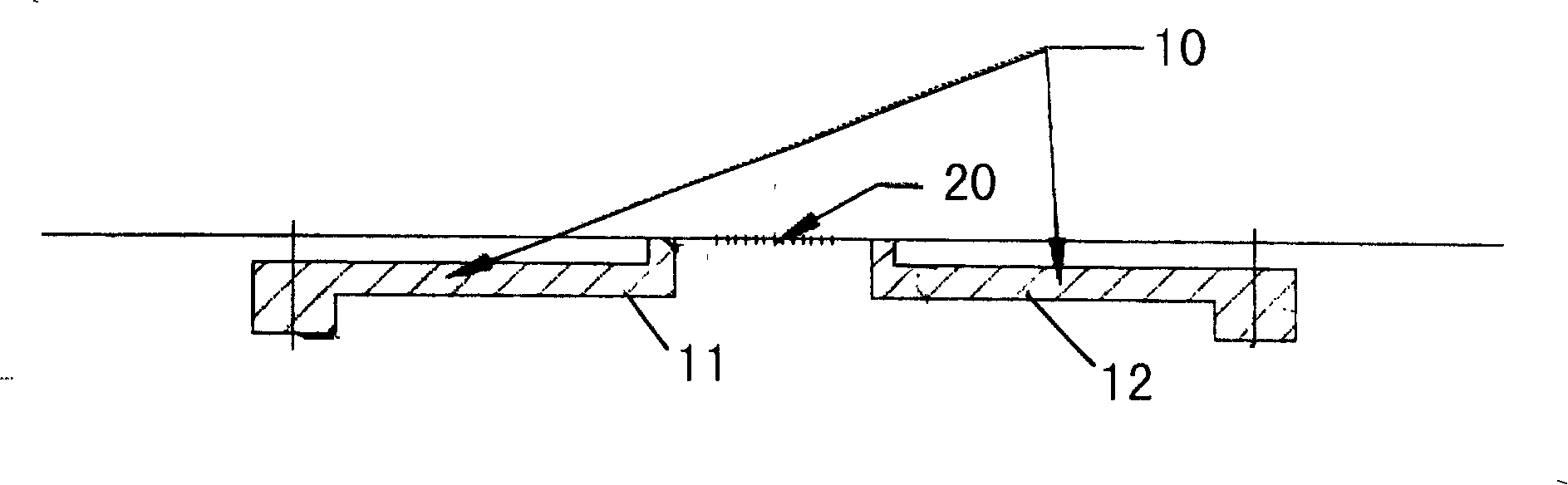
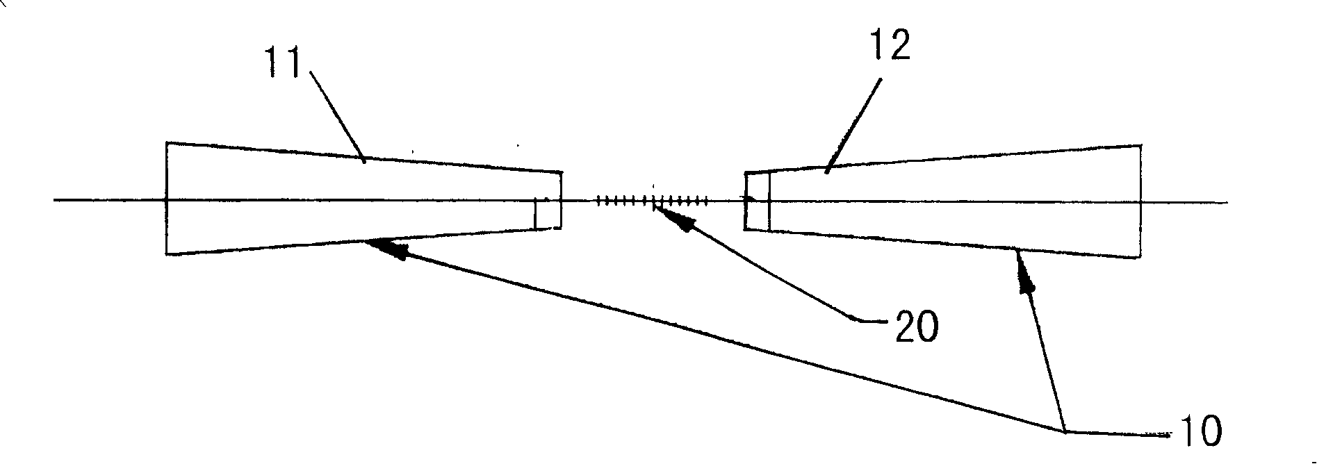
[0025] Such as figure 1 and figure 2 As shown, a fiber grating sensor sensitization structure of the present invention includes:

[0026] A support 10, the support 10 includes left and right support arms 11, 12, the left and right support arms 11, 12 are zigzag structures with opposite directions; a fiber grating 20, the two ends of the fiber grating 20 are fixed on the left and right support arms of the support 10 11, 12; the two ends of the fiber grating 20 are fixed on the lower ends of the left and right arms 11, 12 of the bracket 10 by bonding.

[0027] The other ends of the left and right support arms 11, 12 of the bracket 10 of the present invention are used to be fixedly connected to various sensors.

[0028] ...


PUM


Abstract

The invention relates to a sensitivity enhancing structure of a fiber Bragg grating sensor, which is characterized in that: the invention comprises a support frame which comprises a left support arm and a right support arm which are arranged in Z-shaped structure with inverse directions one another; a fiber Bragg grating two ends of which are fixed on end parts of the left and right support arms of the support frame. The two ends of the fiber Bragg grating are fixed at lower ends of the left and right support arms of the support frame by adopting a bonding method.

Description

technical field [0001] The invention relates to the technical field of optical fiber sensors, in particular to a fiber grating sensor sensitivity enhancement structure. Background technique [0002] Compared with the corresponding conventional sensors, optical fiber sensors have obvious advantages in terms of sensitivity, dynamic range, reliability, etc., especially in the fields of construction, petroleum, and military applications. [0003] Optical fiber sensor is an instrument that uses the light transmission characteristics of optical fiber and various modulation effects generated by its interaction with the surrounding environment to detect physical quantities such as temperature, pressure, and strain in the surrounding environment. Compared with traditional resistive sensors, it has the following main advantages: high pressure sensitivity, no electromagnetic interference, light weight, high temperature resistance, compact structure, high reliability, and information se...

Claims


Application Information

Patent Timeline
Patent Type & Authority Applications(China)
IPC IPC(8): G01D5/353G01D3/02
Inventor 张文涛李芳刘育梁
Owner INST OF SEMICONDUCTORS - CHINESE ACAD OF SCI
Why Eureka
Try Eureka