
Self-adaption optical image high resolution restoration method combining frame selection and blind deconvohtion

An adaptive optics and blind deconvolution technology, applied in the field of image processing, can solve the problems of not considering the wavefront aberration caused by the noise of the wavefront sensor, and not considering the secondary correction of the image, so as to reduce the possibility of falling into an invalid solution , improve the convergence speed and improve the effect of restoration quality

Inactive Publication Date: 2008-06-25
INST OF OPTICS & ELECTRONICS - CHINESE ACAD OF SCI
View PDF0 Cites 13 Cited by
  • Summary
  • Abstract
  • Description
  • Claims
  • Application Information

AI Technical Summary

Benefits of technology

The technical effects provided through this method include improved recovery efficiency during reconstructing high resolution (HR) radar imagery data without sacrificing accuracy or reducing noise levels due to imperfections such as uneven ground conditions caused by waves hitting the surface being scanned. Additionally, there may also help reduce errors when combining different types of sensors together to create accurate 3D maps.

Problems solved by technology

This patents discusses how an algorithm called LYE helps restore sharpness when reconstructing scenes with imperfeled or distorted lenses (images). However, there may still exist some areas where no clear vision has been achieved even if we have good cameras. These areas include edges around windows, corners, etc., affecting visual clarity. To address this problem, algorithms like AutoCorrect were developed specifically designed to enhance edge detection capabilities during reconstruction processes.

Method used


Image

  • Self-adaption optical image high resolution restoration method combining frame selection and blind deconvohtion
  • Self-adaption optical image high resolution restoration method combining frame selection and blind deconvohtion
  • Self-adaption optical image high resolution restoration method combining frame selection and blind deconvohtion

Examples


Embodiment 1

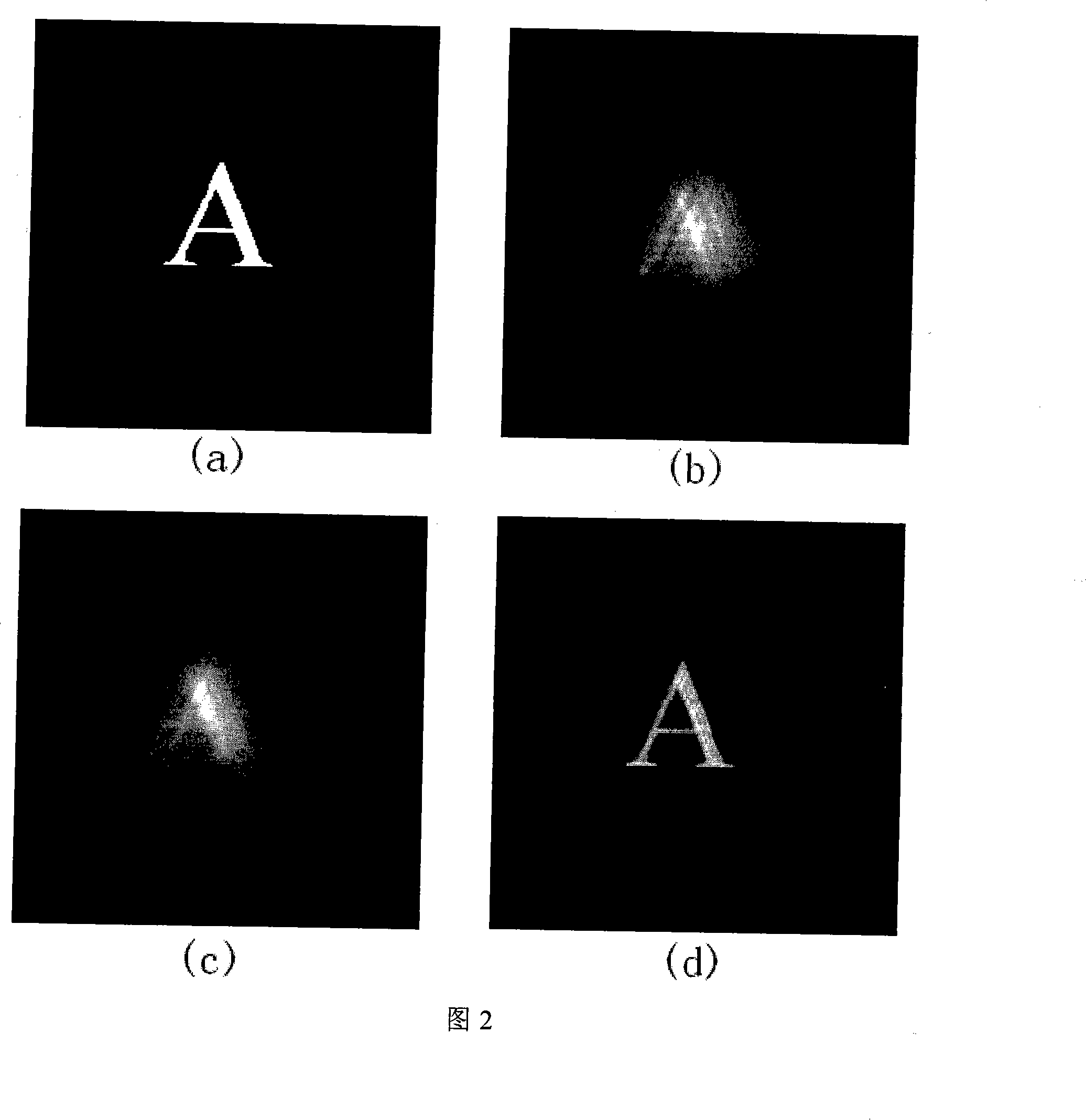
[0049] As shown in Fig. 2, the blurred font is restored by using the present invention. Among them, (a) is the source image, (b)~(c) are two frames selected from 100 frames with noise and degraded image with random disturbance added by frame selection technology, and (d) is the restored image; the result It is shown that the present invention can effectively restore degraded images. The entire calculation process goes through 25 iterations and takes 20 seconds.

Embodiment 2

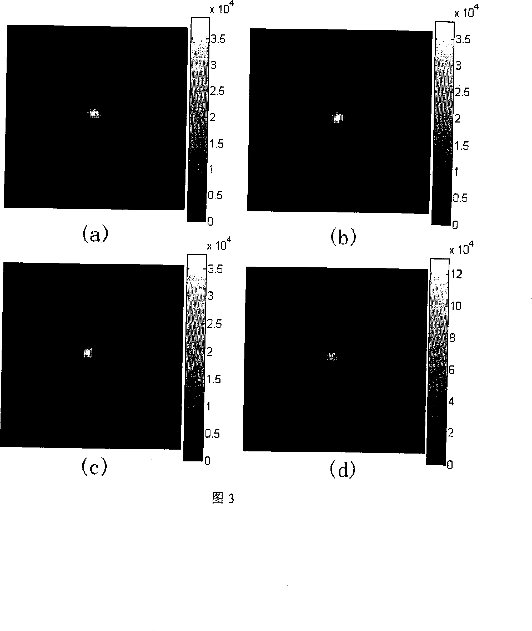
[0051]Applying the present invention to restore the image partially corrected by the adaptive optics system, as shown in FIG. 3 . (a)-(c) are three frames of 100 pixels × 100 pixels adaptive optics corrected star targets after frame selection. (d) is the result after secondary correction by the method of the present invention. Experiments show that the restoration results are better. The entire calculation process took 30 seconds and went through 30 iterations. It can be seen from Figure 3 that under the same energy, the peak value of (d) is 2.56 times, 2.38 and 2.45 times higher than that of (a) ~ (c), which means that the Strehl ratio is increased by 2.56 times , 2.38 and 2.45 times. Figure 4 compares the cross-sectional views of Figure 3(a) and (d).

[0052] For comparison, three frames of images are randomly selected from the short exposure sequence of degraded images for secondary processing, as shown in Figure 4: (a) to (c) are three frames of degraded images randoml...


PUM


Abstract

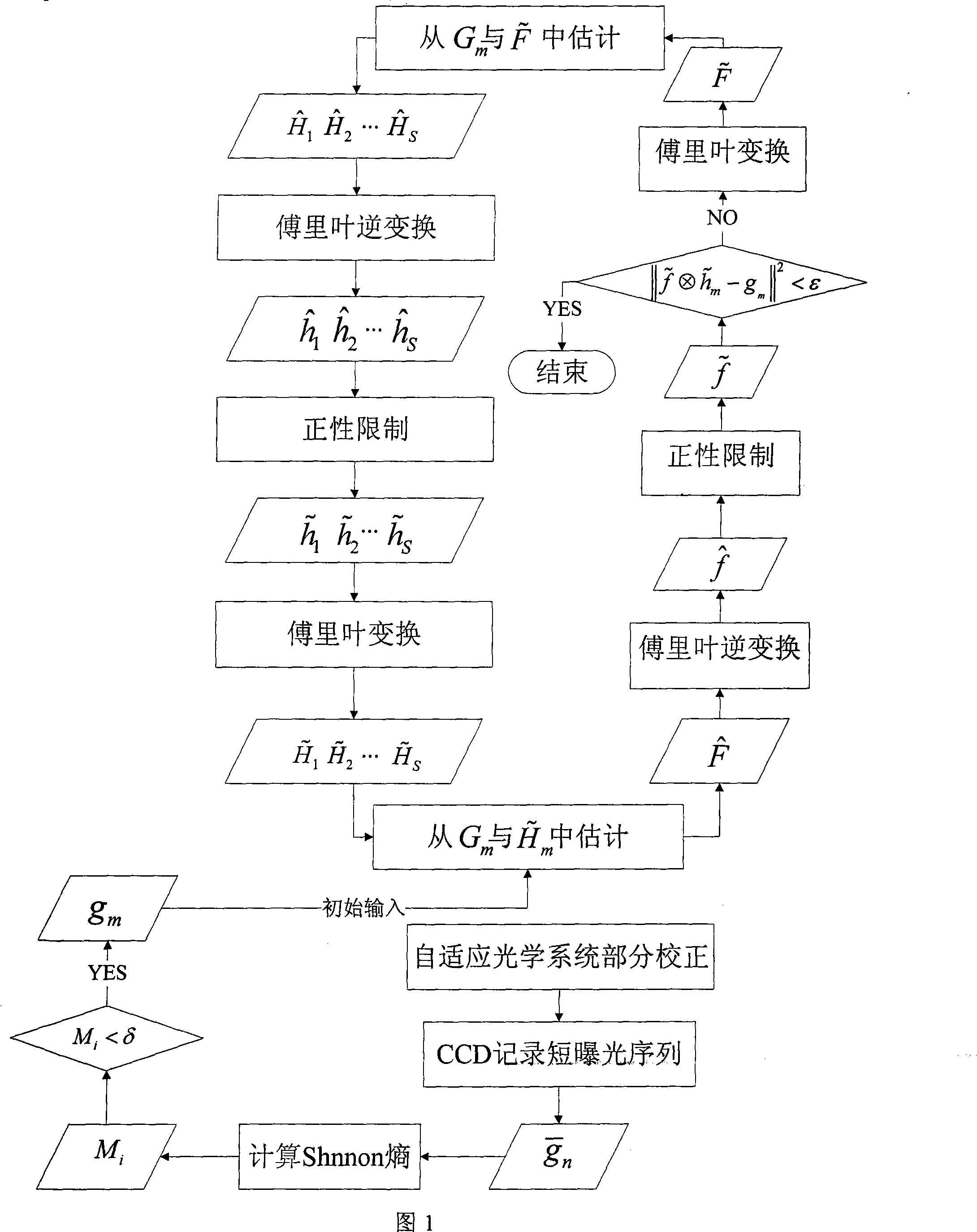
The invention relates to a self-adaptive optical image high resolution restoration method combined with frame selection and blind deconvolution, comprising the following steps: firstly, a short exposure image sequence gn (x, y) is recorded when a self-adaptive optical closed loop is corrected; shannnon entropy of each frame of image in the sequence is calculated; a degraded image gm (x, y) with lower entropy is selected for blind deconvolution image restoration; secondly, an initial value hm (x, y) of a point spread function is generated by utilization of random phase; thirdly, a target f(x, y) is estimated by using the gm(x, y) and the obtained hm (x, y), and an estimated value f(x, y) is obtained after addition of positivity limitation on the target; fourthly, an estimated value hm (x, y) of the point spread function is obtained by using the gm (x, y) and the f(x, y), and an estimated value h(x, y) is obtained after addition of positivity limitation in the same way; fifthly, inspection is made whether an iterated value h(x, y) and an iterated value f(x, y) meet iteration stopping requirements or not; if the iterated values do not meet the iteration stopping requirements, the third step is returned; if the iterated values meet the iteration stopping requirements, circulation is stopped and the f(x, y) and the h(x, y) are outputted. The invention has the advantages of effective improvement of restoration quality, acceleration of convergence rate, capability of well compensating correction capability under hardware limitation of a self-adaptive optical system, and improvement of imaging quality.

Description


Claims


Application Information

Patent Timeline
Owner INST OF OPTICS & ELECTRONICS - CHINESE ACAD OF SCI
Learn More