Multi-frequency antenna

A multi-frequency antenna and frequency technology, applied in the direction of antenna, resonant antenna, independent antenna unit combination, etc., can solve the problems of unfavorable antenna performance and influence, and achieve the effect of good wireless signal transmission and reception efficiency

Active Publication Date: 2011-04-06
WISTRON NEWEB
View PDF0 Cites 0 Cited by
  • Summary
  • Abstract
  • Description
  • Claims
  • Application Information

AI Technical Summary

Problems solved by technology

However, when the antenna is built into a small computer device with limited space, it may have an adverse effect on the performance of the antenna
However, all kinds of portable computer devices are manufactured in the direction of lightness, lightness and shortness, so the built-in antenna must match the space of the portable computer device to design an appropriate structure and provide sufficient antenna efficiency

Method used


Image

  • Multi-frequency antenna
  • Multi-frequency antenna
  • Multi-frequency antenna

Examples


Embodiment Construction

[0039] An embodiment of the present invention is a multi-frequency antenna, which can be installed on portable electronic devices with wireless communication functions, such as notebook computers, personal digital assistants (PDAs), and the like. This kind of multi-frequency antenna can receive signals of at least two frequency bands. For the sake of convenience, unless otherwise specified, the two frequency bands are represented by their center frequencies, that is, the first frequency and the second frequency. Anyone skilled in the art can change different parameters of the antenna design according to their needs, so as to meet different application ranges.

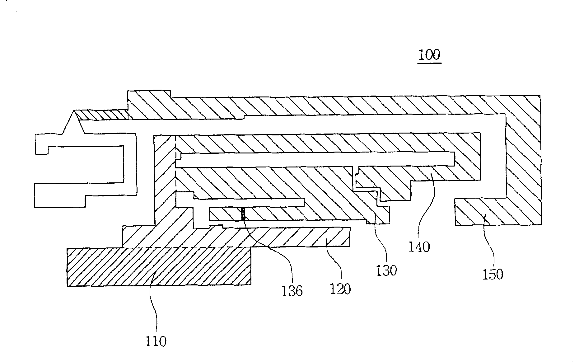
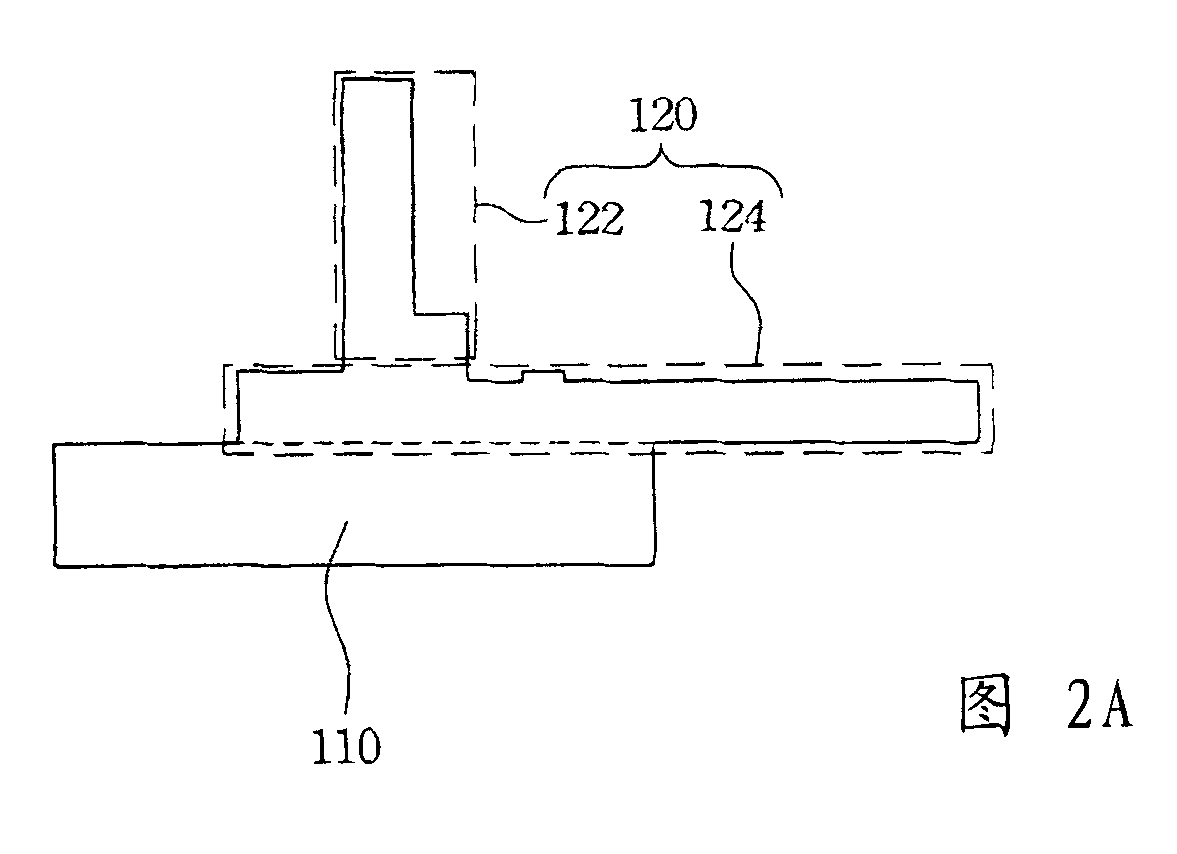
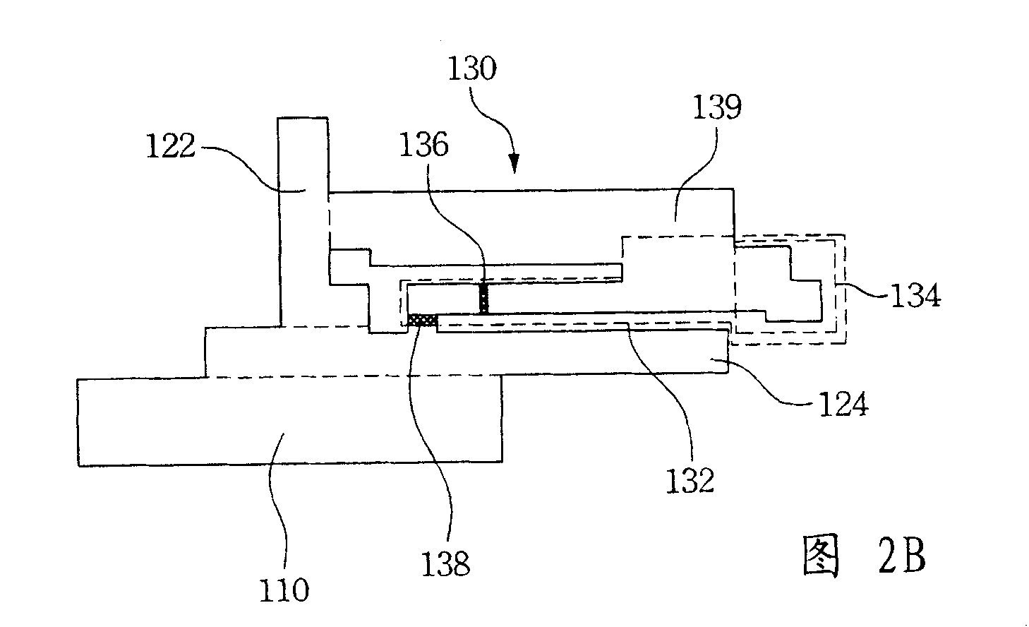
[0040] Please refer to figure 1 , which is a plane expanded view of the multi-frequency antenna according to the embodiment of the present invention. The multi-frequency antenna 100 of the present embodiment has a grounding part 110 , a first conducting element 120 , a first radiating part 130 , and a second radiating ...


PUM


Abstract

The invention relates to a multi-frequency antenna, which is used for receiving the signals of a first frequency and a second frequency. The invention at least comprises a grounding part, a first conducting component, a first radiation part and a second radiation part. The first conducting component is mutually connected with the grounding part. The first radiation part and the second radiation part are respectively connected on the first conducting component. In addition, the multi-frequency antenna also comprises a parasitic structure surrounding the second radiation part, and the parasiticstructure is mutually connected with the grounding part.

Description

technical field [0001] The present invention relates to an antenna structure, and in particular to a multi-frequency antenna structure. Background technique [0002] Connection and communication between various wireless networks or system devices such as wireless personal area network (WPAN), wireless local area network (WLAN), and wireless wide area network (WWAN), All can be realized by the antenna device installed therein. [0003] Generally speaking, the antennas of various wireless devices can be designed as external connections or built into the devices. For example, some notebook computers will set the external antenna on the top of the screen, or design the external antenna on the PCMCIA card, and communicate with the computer through this interface. Such an external antenna design may require high cost and be easily damaged due to being exposed to the external environment. In another design, the antenna is directly built into the notebook computer. [0004] The ...

Claims


Application Information

Patent Timeline
Patent Type & Authority Patents(China)
IPC IPC(8): H01Q5/00H01Q21/30H01Q9/30H01Q1/38H01Q5/20H01Q5/364H01Q5/378
Inventor 赖颖俊黄俊铭曾冠学
Owner WISTRON NEWEB
Why Eureka
Try Eureka