
Electric machine fixation structure of linear compressor

A technology of linear compressors and linear motors, applied in electromechanical devices, machines/engines, magnetic circuit shapes/styles/structures, etc., can solve problems such as increasing assembly force limitations, complicated manufacturing processes, and reducing operational reliability, etc., to achieve improved Productivity, simplification of manufacturing process, and improvement of operational reliability

Inactive Publication Date: 2008-06-25
TAIZHOU LG ELECTRONICS REFRIGERATOR CO LTD
View PDF0 Cites 12 Cited by
  • Summary
  • Abstract
  • Description
  • Claims
  • Application Information

AI Technical Summary

Problems solved by technology

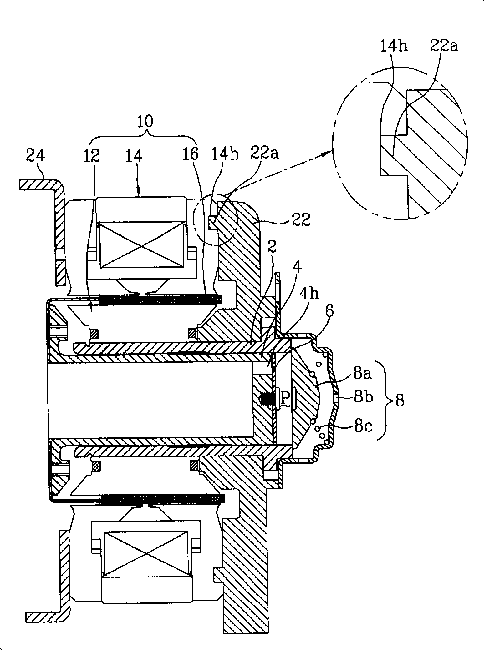
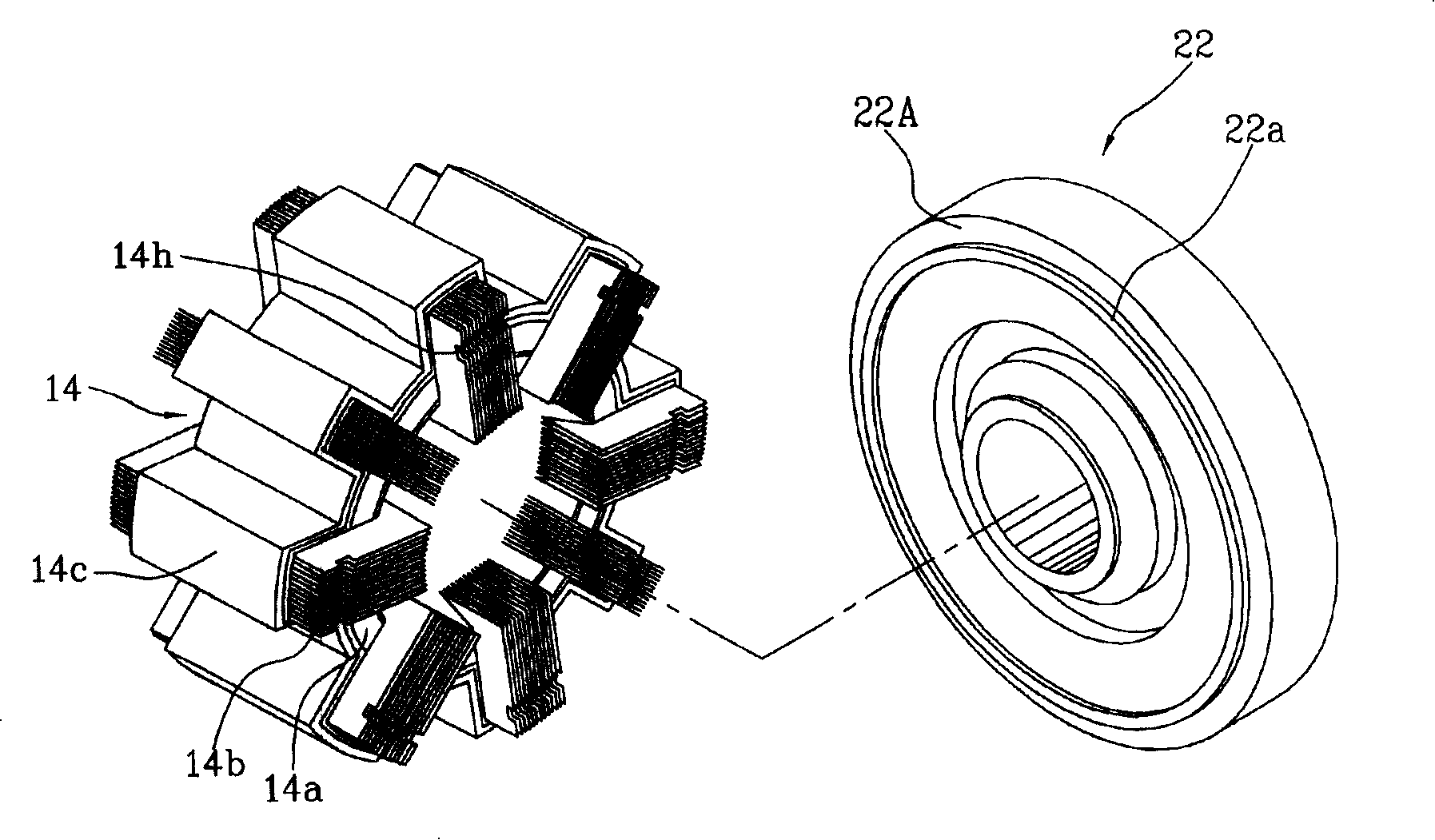
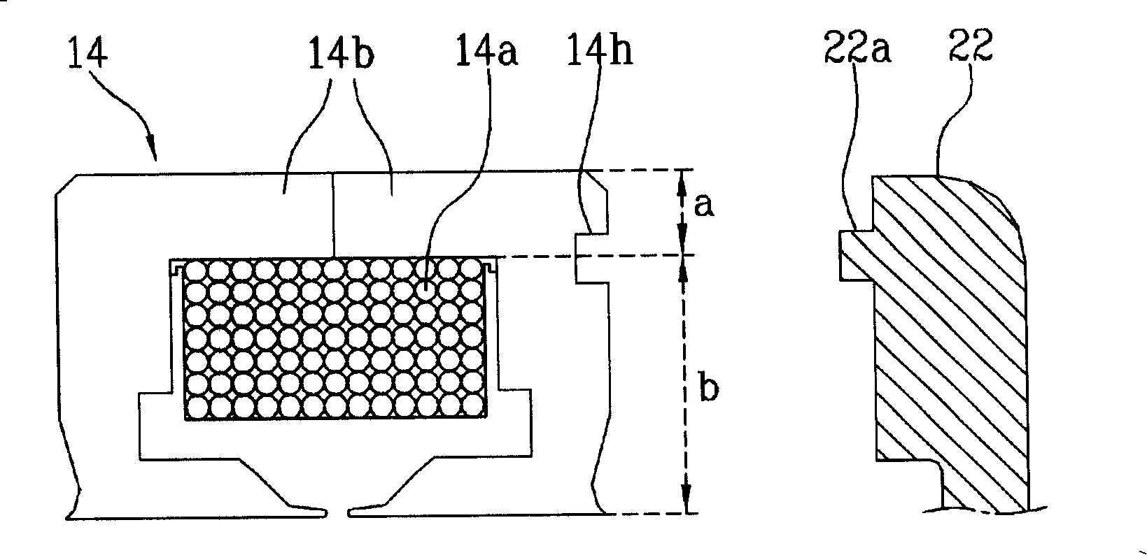
[0014] However, in the prior art linear compressor fixing structure, when the outer stator 14 provided with the coil group 14b fixed around the coil winding body 14a is arranged between the main body frame 22 and the motor cover 24, the coil group In the state where the fixing protrusion 22a formed on one side 22A of the main body frame is inserted into the fixing groove 14h formed in the central part of one end of the coil group 14b, one end of the coil group 14b is supported on the main body frame 22, thereby being fixed. The slot straddles the straight section section a and the installation slot section b provided in one end of the coil group 14b. When the outer stator 14 is installed on the main body frame 22 and the motor cover 24, the assembly force only acts on the The linear part section a in the coil group 14b, so the lifting assembly force is limited, thereby reducing the reliability of operation
In order to provide the fixing groove 14h on the coil group, it is necessary to laminate the laminated structures in which the groove is formed at one end in the circumferential direction, so the manufacturing process is very complicated.

Method used


Image

  • Electric machine fixation structure of linear compressor
  • Electric machine fixation structure of linear compressor
  • Electric machine fixation structure of linear compressor

Examples


Embodiment Construction

[0030] Below, the content of the embodiments of the present invention will be described in detail in conjunction with the accompanying drawings.

[0031] Figure 4 is a side sectional view of the linear compressor provided by the present invention, Figure 5 as well as Image 6 It is a partial exploded perspective view and an exploded cross-sectional view of the linear motor fixing structure of the linear compressor provided by the present invention.

[0032] The linear compressor provided by the present invention is as Figure 4 As shown, the linear motor 60 structure composed of cylinder 52, piston 54, inner stator 62, outer stator 64 and permanent magnet 66 is supported by a buffer spring (not shown) inside the sealed space of the housing (not shown). , while one end of the cylinder 52 is fixed on the main body frame 72, one end of the piston 54 is inserted into its inner side, thereby forming an internal compression space P, and the inner stator is fixed on the outer pe...


PUM


Abstract

The invention provides a linear motor fixed structure of a linear compressor; the structure comprises a cylinder, a piston, an inner stator, an outer stator, a permanent magnet, a supporting projection that supports one end of the outer stator and projects out of one surface of a main frame and a motor cover that supports the other end of the outer stator and is fixed on the main frame, wherein, the number of the supporting projection that projects out of one surface of the main frame is one or more. The invention has the effects that: in the linear motor fixed structure of the linear compressor, when the other end on the axial direction of a coil group in the outer stator is supported on the motor cover, at least one supporting projection is supported in a straight-line-part section that is free from a coil winding in the coil group, so that the centralized gravity acts on a contact surface, thereby obtaining a linear motor that carries out the fixed linear compressor much more stably. The invention not only can improve the operation reliability of the motor, but also can simplify the production process and improve the production since the coil group is not provided with a fixed groove.

Description

technical field [0001] The invention relates to a linear motor structure, in particular to a motor fixing structure of a linear compressor. Background technique [0002] figure 1 is a partial side sectional view of a prior art linear compressor, figure 2 as well as image 3 It is a partially exploded perspective view and an exploded cross-sectional view of a linear motor fixing structure of a linear compressor in the prior art. [0003] Prior art linear compressors such as figure 1 As shown, one end of the piston 4 is inserted into the inner side of the cylinder 2, and a compression space P is formed inside. The piston 4 performs linear reciprocating motion when the linear motor 10 is started, sucks the refrigerant into the compression space P, compresses it, and then discharges it. While one end of the cylinder 2 is fixed on the main frame 22 , the linear motor 10 is supported on the main frame 22 by a motor cover 24 . [0004] The cylinder 2, the piston 4 and the lin...

Claims


Application Information

Patent Timeline
Patent Type & Authority Applications(China)
IPC IPC(8): H02K33/18H02K7/14H02K1/18F04B17/03F04B17/04
Inventor 姜亮俊李敏雨尹亨杓姜庆石
Owner TAIZHOU LG ELECTRONICS REFRIGERATOR CO LTD
Learn More