Light emitting device for AC power operation

A light-emitting device and electric power technology, applied in circuits, electrical components, instruments, etc., can solve problems such as eye fatigue, inability to emit light uniformly, and flickering effects

Active Publication Date: 2008-06-25
SEOUL VIOSYS CO LTD
View PDF6 Cites 35 Cited by
  • Summary
  • Abstract
  • Description
  • Claims
  • Application Information

AI Technical Summary

Problems solved by technology

Therefore, uniform light cannot be continuously emitted on a substrate, and flickering effects will occur
This flicker effect will be noticeable when viewing a moving object at a certain distance from

Method used


Image

  • Light emitting device for AC power operation
  • Light emitting device for AC power operation
  • Light emitting device for AC power operation

Examples


Embodiment Construction

[0096] Hereinafter, preferred embodiments of the present invention will be described in detail with reference to the accompanying drawings. The following embodiments are provided for the purpose of illustration only, so that those skilled in the art can fully understand the spirit of the present invention. Therefore, the present invention is not limited to the following embodiments, but the present invention can be implemented in other forms. In these drawings, dimensions such as width, length, and thickness of each element will be exaggerated for convenience of illustration. Throughout the specification and drawings, the same reference numerals designate the same elements.

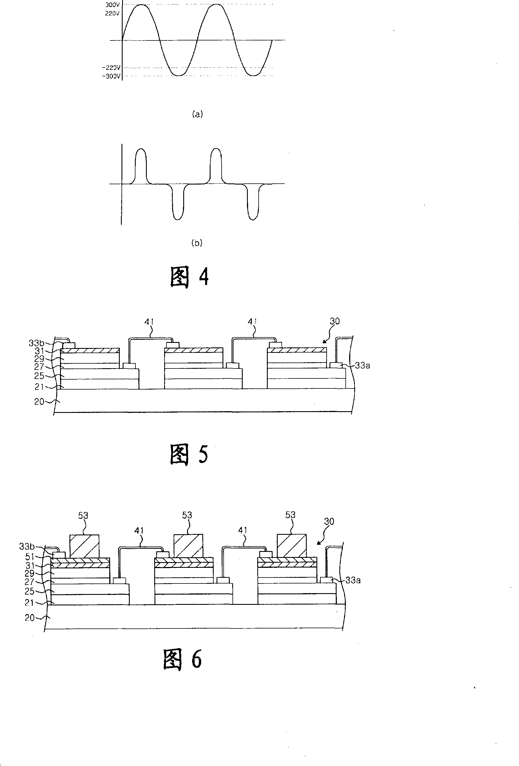
[0097] FIG. 5 is a partial cross-sectional view of a light emitting diode (LED) according to an embodiment of the present invention.

[0098] Referring to FIG. 5 , some light emitting units 30 spaced apart from each other are positioned on a base 20 . Each light emitting unit 30 includes a first conduc...


PUM


Abstract

Disclosed is an improved light-emitting device for an AC power operation. A conventional light emitting device employs an AC light-emitting diode having arrays of light emitting cells connected in reverse parallel. The arrays in the prior art alternately repeat on/off in response to a phase change of an AC power source, resulting in short light emission time during a 1/2 cycle and the occurrence of a flicker effect. An AC light-emitting device according to the present invention employs a variety of means by which light emission time is prolonged during a 1/2 cycle in response to a phase changeof an AC power source and a flicker effect can be reduced. For example, the means may be switching blocks respectively connected to nodes between the light emitting cells, switching blocks connectedto a plurality of arrays, or a delay phosphor. Further, there is provided an AC light-emitting device, wherein a plurality of arrays having the different numbers of light emitting cells are employed to increase light emission time and to reduce a flicker effect.

Description

technical field [0001] The present invention relates to a lighting device, and more particularly to a lighting device for alternating current (AC) power operation, the lighting device having an array of series-connected lighting units. Background technique [0002] A light emitting diode (LED) is an electroluminescent device having a structure in which an N-type semiconductor and a P-type semiconductor are bonded together, and emits light through recombination of electrons and holes. Such LEDs are widely used in displays and backlight modules. In addition, since LEDs have less power consumption and a longer lifespan than conventional light bulbs and fluorescent lamps, the field of application of LEDs has been expanded to use them for general lighting while replacing traditional Incandescent light bulbs and fluorescent lights. [0003] Under alternating current (AC) power, the LED is repeatedly turned on (on) / off (off) according to the direction of the current. Therefore, ...

Claims


Application Information

Patent Timeline
IPC IPC(8): H01L33/00
CPCY02B20/42G09G3/14G09G3/32H01L33/00
Inventor 李贞勋詹姆士·S·史贝克金洪山金载助金成翰李在皓
Owner SEOUL VIOSYS CO LTD
Why Eureka
Try Eureka