Electrical connector

一种电连接器、电端子的技术,应用在连接、电路、连接装置的零部件等方向,能够解决端子脱开等问题,达到小端子插入力、良好防端子脱开性的效果

Active Publication Date: 2008-06-25
APTIV TECH LTD
View PDF0 Cites 8 Cited by
  • Summary
  • Abstract
  • Description
  • Claims
  • Application Information

AI Technical Summary

Problems solved by technology

[0009] This in turn can lead to undesired disengagement of the terminals

Method used


Image

  • Electrical connector
  • Electrical connector
  • Electrical connector

Examples


Embodiment Construction

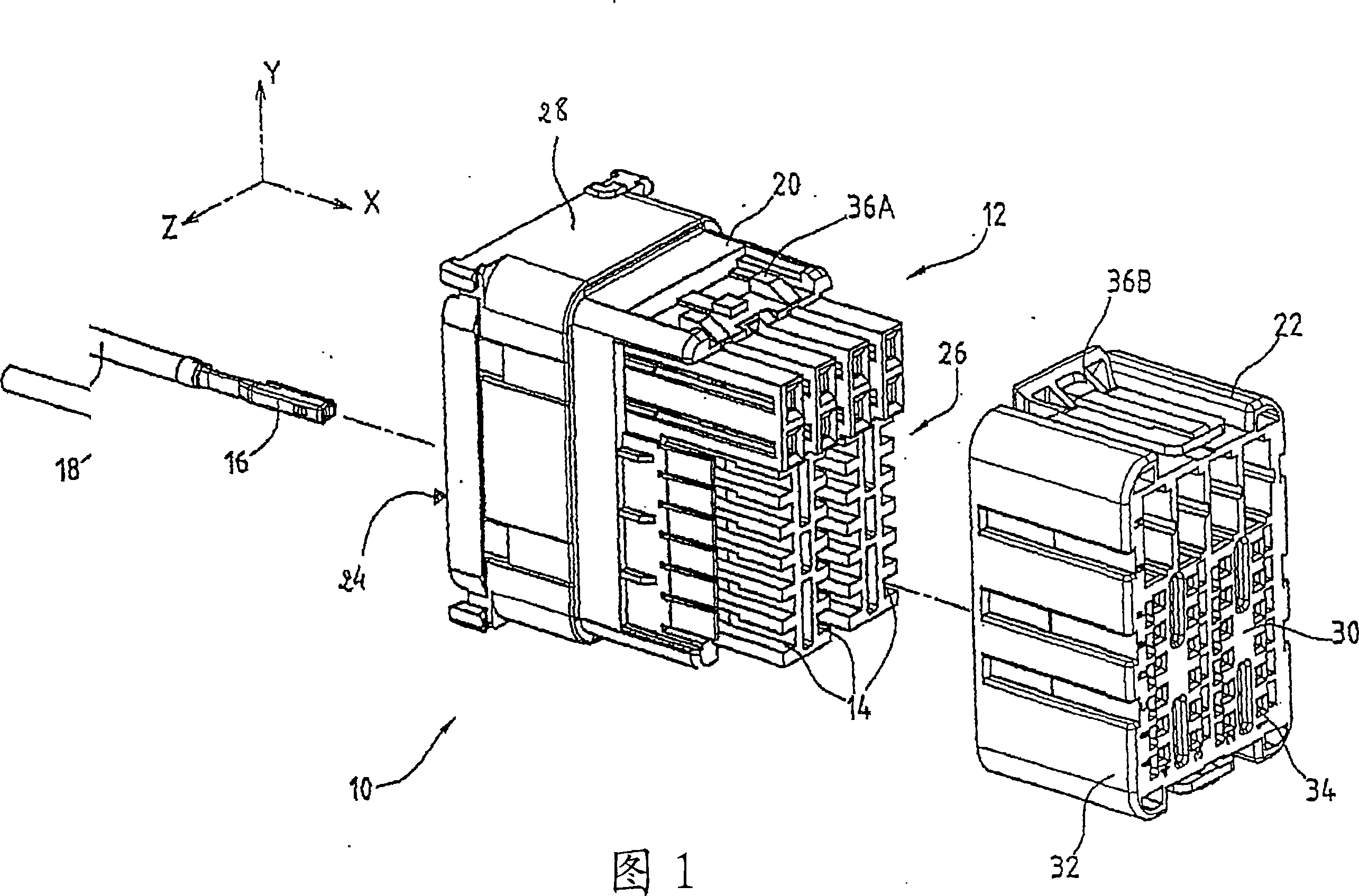
[0028] Figure 1 shows an electrical connector 10 for mating with a mating connector (not shown) carrying a set of pins.

[0029] In the figures, the mating direction refers to the X-axis, which is oriented from the connector 10 towards the counter-connector.

[0030] The electrical connector 10 includes a housing 12 with a set of terminal receiving cavities 14 formed therein and electrical terminals 16 crimped to wires 18 . Only one of the terminals is shown in the figure.

[0031] The terminals 16 are of a well-known form of clamp and are therefore not further described.

[0032] Two parts of the housing are shown as the body 20 and the locking element 22 .

[0033] The body 20 has a generally box-like shape with a rear surface 24 for insertion of the terminal 16 and a front surface 26 for being covered by the locking element 22 .

[0034] The rear surface 24 is surrounded by a protective skirt 28 and is drilled with terminal insertion holes (not visible), each opening int...


PUM


Abstract

The electrical connector comprises an electrical terminal (16), a housing (12) delimiting a chamber (14) for receiving the terminal (16) along a reception direction (X), successively at a reception position and at a retained position, a pawl (44) hinged to one amongst the housing (12) and the terminal (16), and a stop (50) fixed to the other amongst the housing (12) and the terminal (16). Said pawl (44) and stop (50) cooperate for retaining the terminal (16) at its retained position, and said housing (12) comprises a guiding wall (42) with an guiding surface on which the terminal (16) is pushed against by the pawl (44) being elastically pushed back. The guiding surface comprises a raising slope (64) inclined toward the inside of the chamber (14) along the reception direction (X) 1 the slope being located to be climbed on by the terminal (16) pushed from its reception position to its retained position. Application in the automotive industry.

Description

technical field [0001] The present invention relates to an electrical connector for connecting wires to pins, in particular to a connector used in the automotive industry. Background technique [0002] A connector includes a support housing that carries a set of terminals, each of which is integrally crimped with a wire. The connector thus obtained is intended to be connected to a set of pins carried, for example, by a circuit board, each pin being in contact with a terminal. [0003] To install the connector, each terminal is first crimped onto the wire, and then the terminal is inserted into the receiving cavity of the housing. In this cavity, the terminals are held by the claws and stops. Usually the claw is hinged on the housing and the stop is arranged on the terminal, although the claw may be hinged on the terminal. [0004] There are several issues with the current connector. [0005] During insertion of the terminal, the terminal hits the base of the claw to elas...

Claims


Application Information

Patent Timeline
Patent Type & Authority Applications(China)
IPC IPC(8): H01R13/422
CPCH01R13/4223H01R13/422
Inventor 弗雷德里克·沙佐特克利斯汀·坎普福特
Owner APTIV TECH LTD
Why Eureka
Try Eureka