Device and method for detecting cutting tool state

A state detection device and state detection technology are applied in manufacturing tools, measuring/indicating equipment, positioning measurement in boring machines/drilling machines, etc., which can solve problems such as increasing non-processing strokes and affecting drilling speed, and achieve faster drilling speed , The effect of shortening the non-processing stroke

Inactive Publication Date: 2008-07-02
IND TECH RES INST
View PDF0 Cites 15 Cited by
  • Summary
  • Abstract
  • Description
  • Claims
  • Application Information

AI Technical Summary

Problems solved by technology

However, the above-mentioned light interruption method, carbon brush contact method, dust and debris collection method, voltage signal method or driving current method al

Method used


Image

  • Device and method for detecting cutting tool state
  • Device and method for detecting cutting tool state
  • Device and method for detecting cutting tool state

Examples


Example Embodiment

[0049] The following describes the implementation of the present invention through specific specific examples, and those skilled in the art can easily understand other advantages and effects of the present invention from the content disclosed in this specification.

[0050] See Figure 1 to Figure 3 , Is a specific embodiment of the tool state detection device and method of the present invention. In this embodiment, the application in drilling operations is taken as an example. Therefore, drills are used to represent tools. However, those skilled in the art can understand that the present invention is not limited to applications in drilling operations, and the tools referred to are not drilled Is limited.

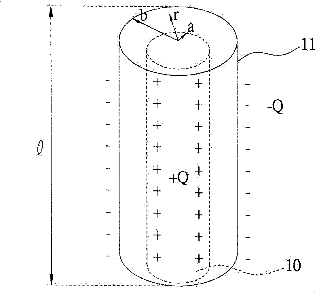
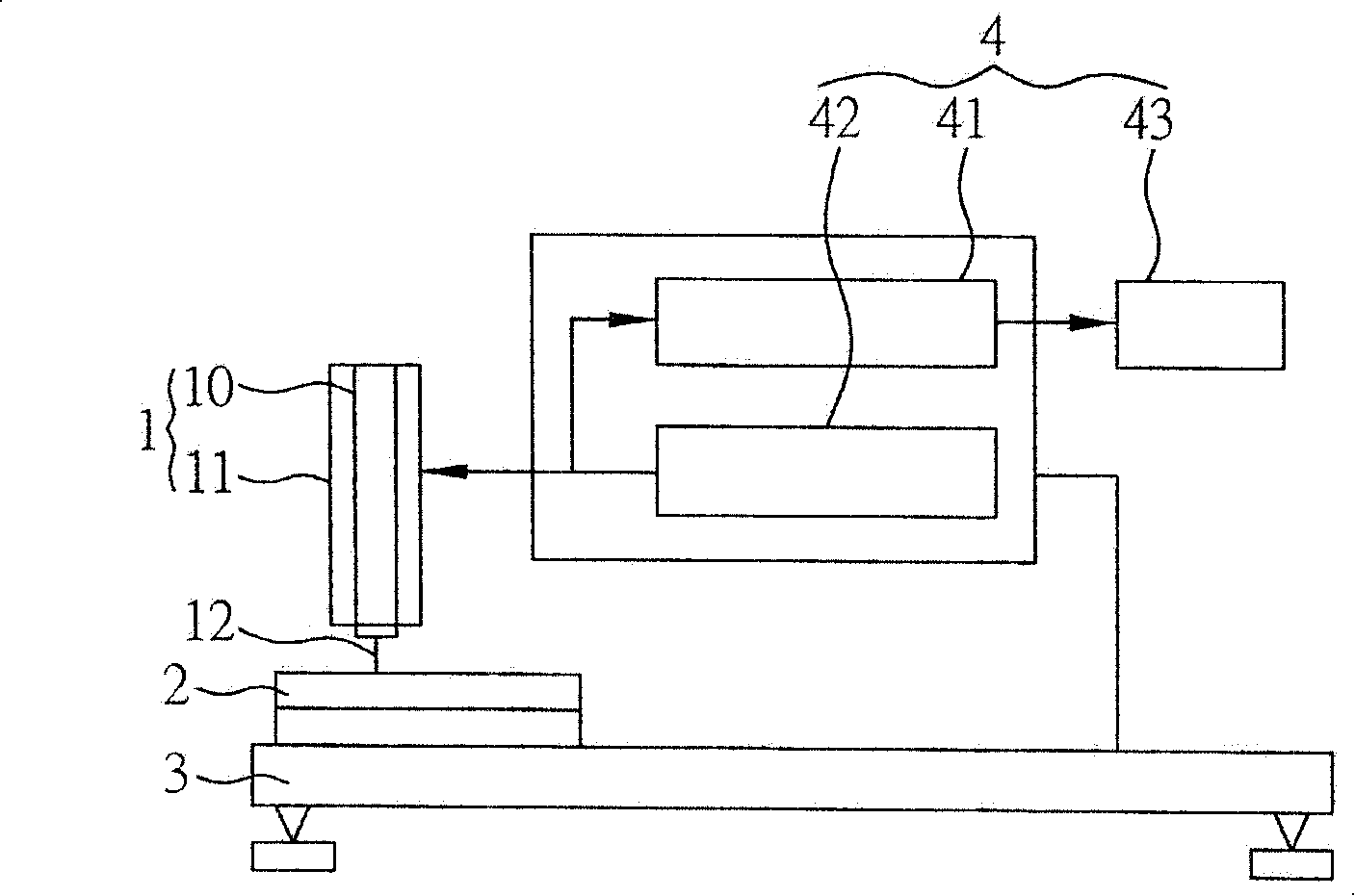
[0051] Such as figure 1 As shown, the spindle motor 1 has a central rotor 10 and a housing 11 surrounding the central rotor 10. When the central rotor 10 is in operation, the spindle motor 1 introduces air between the central rotor 10 and the housing 11 so that the central roto...


PUM


Abstract

The invention provides a cutter state detection device and a method used for detecting the state of a cutter which processes a workpiece. The workpiece is arranged on a processing machine station; the cutter is driven to rotate by a central rotor of a mainshaft motor. The central rotor of the mainshaft motor keeps insulation with a shell of the mainshaft motor; an induction electric field between the shell and the central rotor is generated mainly by an electric field signal which is acted on the shell; furthermore, the induction electric field is detected whether to exist in the processing operation. When the signal of the induction electric field disappears as the cutter is contacted with the workpiece and the processing machine station is grounded, the non-broken cutter state is detected; when the signal of the induction electric field exists continuously, the broken cutter state is detected.

Description

technical field [0001] The present invention relates to a tool state detection device and method, and more specifically, to a tool state detection device and method for detecting whether a tool is worn or broken during processing operations on a workpiece. Background technique [0002] When using automated processing tools for processing operations, it is necessary to detect the status of the tool in real time to ensure product quality. Taking the drilling operation of printed circuit boards as an example, it is realized by clamping the drill needle with a high-speed non-contact pneumatic spindle motor. The drilling machine has high performance such as fast, stable and accurate. However, the drill pin will wear out or even break the knife under high-speed operation. In order to detect and replace in time when the drill is worn or broken, in the past, a sensing device was installed near the bottom of the non-contact motor relative to the tip of the drill. When the state of ...

Claims


Application Information

Patent Timeline
IPC IPC(8): B23Q17/09B23B49/00
Inventor 张汉杰
Owner IND TECH RES INST
Why Eureka
Try Eureka