
Embedded forming method and mold for embedded forming

A technology of insert molding and mold, applied in the direction of coating, etc., can solve problems such as deformation of integrated products, deformation of secondary injection molded products, and rupture of secondary injection molded products.

Inactive Publication Date: 2008-07-09
FUJISEIKO
View PDF1 Cites 9 Cited by
  • Summary
  • Abstract
  • Description
  • Claims
  • Application Information

AI Technical Summary

Problems solved by technology

[0003]However, when inserting an injection molded product, that is, an insert (primary molded product), and molding it into an integrated product by secondary injection molding, when the embedded When the part shrinks or the insert is a deformed product determined by the shape of the final product, the stress deformation of the insert will have an adverse effect on the secondary injection molded product, resulting in deformation of the secondary injection molded product
In addition, due to the shrinkage of the secondary injection molded product, cracking of the secondary injection molded product and deformation of the integrated product may occur

Method used


Image

  • Embedded forming method and mold for embedded forming
  • Embedded forming method and mold for embedded forming
  • Embedded forming method and mold for embedded forming

Examples


Embodiment Construction

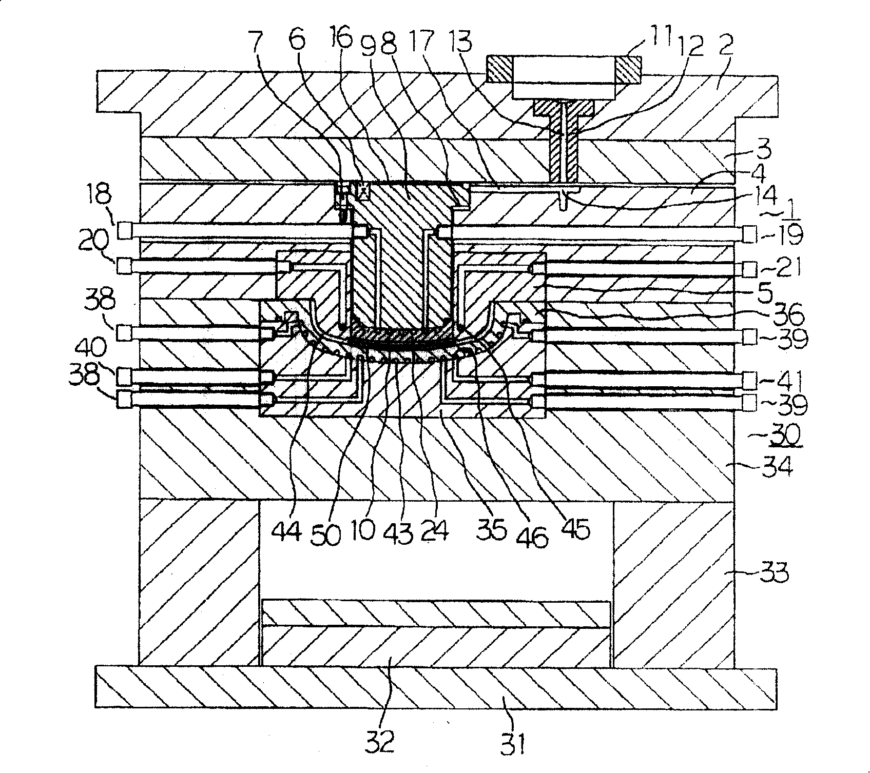
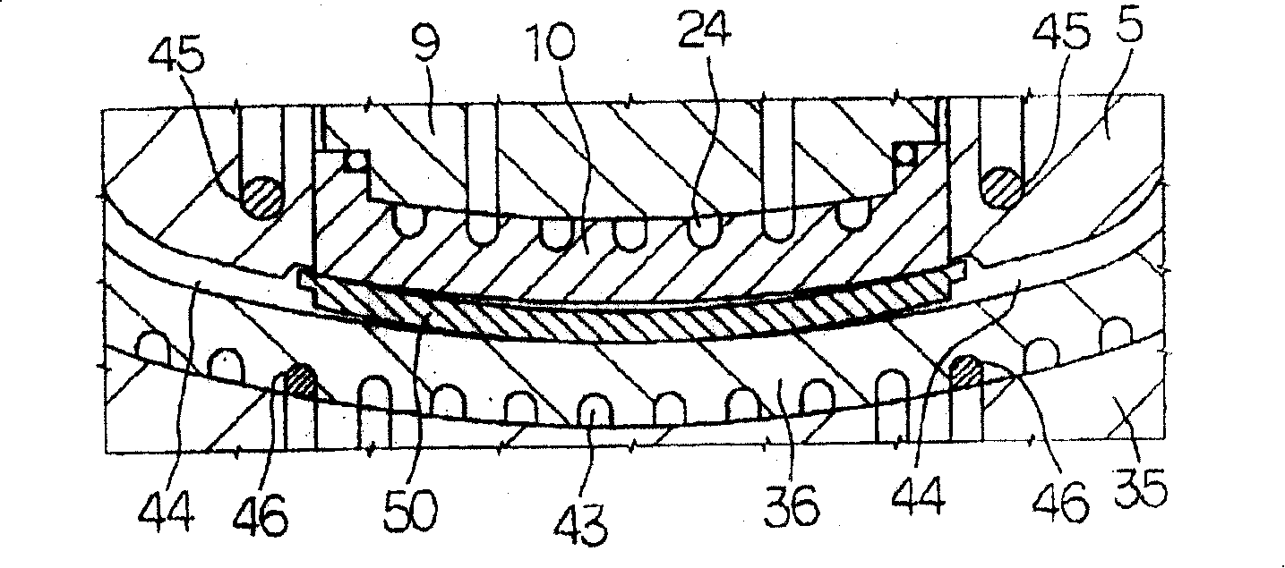
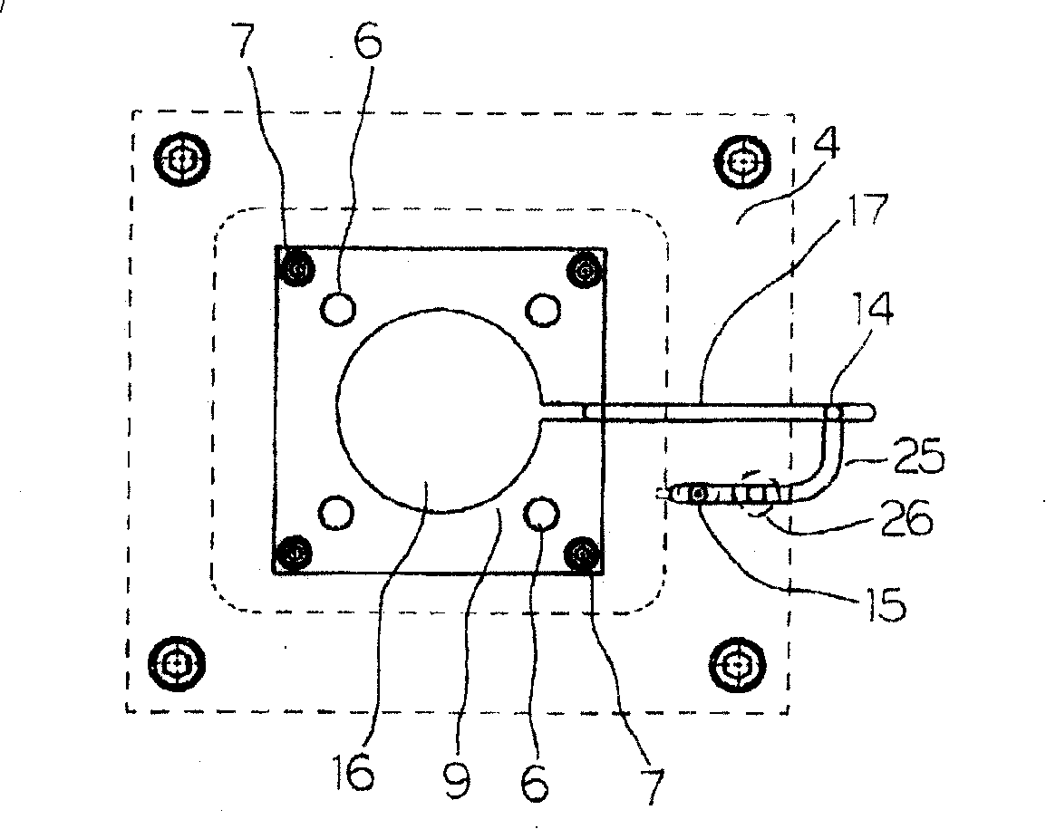
[0112] Below, according to Figure 1 to Figure 9 , to describe the first embodiment for carrying out the present invention. First, according to Figure 1 to Figure 4 , illustrating the overall structure of the mold. figure 1 It is a fixed-side assembly mounted on a fixed platen (not shown) with bolts. The fixed side assembly 1 includes: the first fixed side base plate (base plate) 2 positioned at the top; the second fixed side base plate 3 fixed on the first fixed side base plate 2 by screws; The bottom plate 3 is connected or separated from the fixed side third bottom plate 4; the male die (Male Die) 5 is fitted in the recess of the fixed side third bottom plate 4 and fixed on the fixed side third bottom plate 4; the bushing base 9 , it runs through a plurality of support rods 7 with heads and the lower ends of these support rods 7 are fixed on the third bottom plate 4 on the fixed side, and the bushing base 9 can be placed on the opening of the third bottom plate 4 on the...


PUM


Abstract

The invention is to solve the problem that when embedded parts are embedded, and a secondary injection moulding mode is used to mould the embedded parts which become an integrated product, the secondary injected and moulded product and the integrated product are not caused to deform as far as possible. After embedded parts (50A) made of thermoplastic synthetic resin are arranged inside a mould under the state of breaking the mould, the mould is closed. A bush (10A) is used to extrude the embedded parts (50A) into a female die (36). Subsequently, the embedded parts (50A) are heated up and softened. On one hand, the bush (10A) is moved far from the female die(36); on the other hand, the composite resin material flows into and is injected into the bush (10A) before the composite resin material is guided inside a mould cavity (44A) between a male die (5A) and the female die (36) so as to cool and harden the connected embedded parts (50A) and the secondary moulded products (51A) by cooling the surface of the male die (5A) and the female die (36).

Description

technical field [0001] The present invention relates to an insert molding method and a mold for insert molding. Background technique [0002] The technique of inserting an injection molded product, that is, an insert (primary molded product) and molding it into an integrated product by secondary injection molding is well known (for example, refer to Japanese Patent Laid-Open No. 2002-347067). [0003] However, when inserting an injection molded product, that is, an insert (primary molded product) and molding it into an integrated product by secondary injection molding, when the insert shrinks or the insert is deformed according to the shape of the final product During the product, the stress deformation of the insert will have an adverse effect on the secondary injection molded product, resulting in deformation of the secondary injection molded product. In addition, due to the shrinkage of the secondary injection molded product, cracks of the secondary injection molded prod...

Claims


Application Information

Patent Timeline
IPC IPC(8): B29C45/14B29C45/26B29C45/33B29C45/72B29C45/73B29C45/17
Inventor 横山勝助金子光雄
Owner FUJISEIKO
Learn More