Inserting type fishplate-free rail joint connector

A joint connector and fish plate technology, which is applied to the joints, tracks, roads and other directions of rails, can solve the problems of large assembly workload, peeling, and buckle, and achieve reasonable structural design, small maintenance workload, and bearing capacity. strong effect

Inactive Publication Date: 2008-07-09
陈力求
View PDF0 Cites 7 Cited by
  • Summary
  • Abstract
  • Description
  • Claims
  • Application Information

AI Technical Summary

Problems solved by technology

[0003] The purpose of the present invention is to provide a plug-in connector for rail joints without fishplates, which can solve the problems of easy cracking at the bolt holes of fishplate rails and fatigue damage of rail joints when the fishplate connection method is used for railway rail joint

Method used


Image

  • Inserting type fishplate-free rail joint connector
  • Inserting type fishplate-free rail joint connector
  • Inserting type fishplate-free rail joint connector

Examples


specific Embodiment approach 1

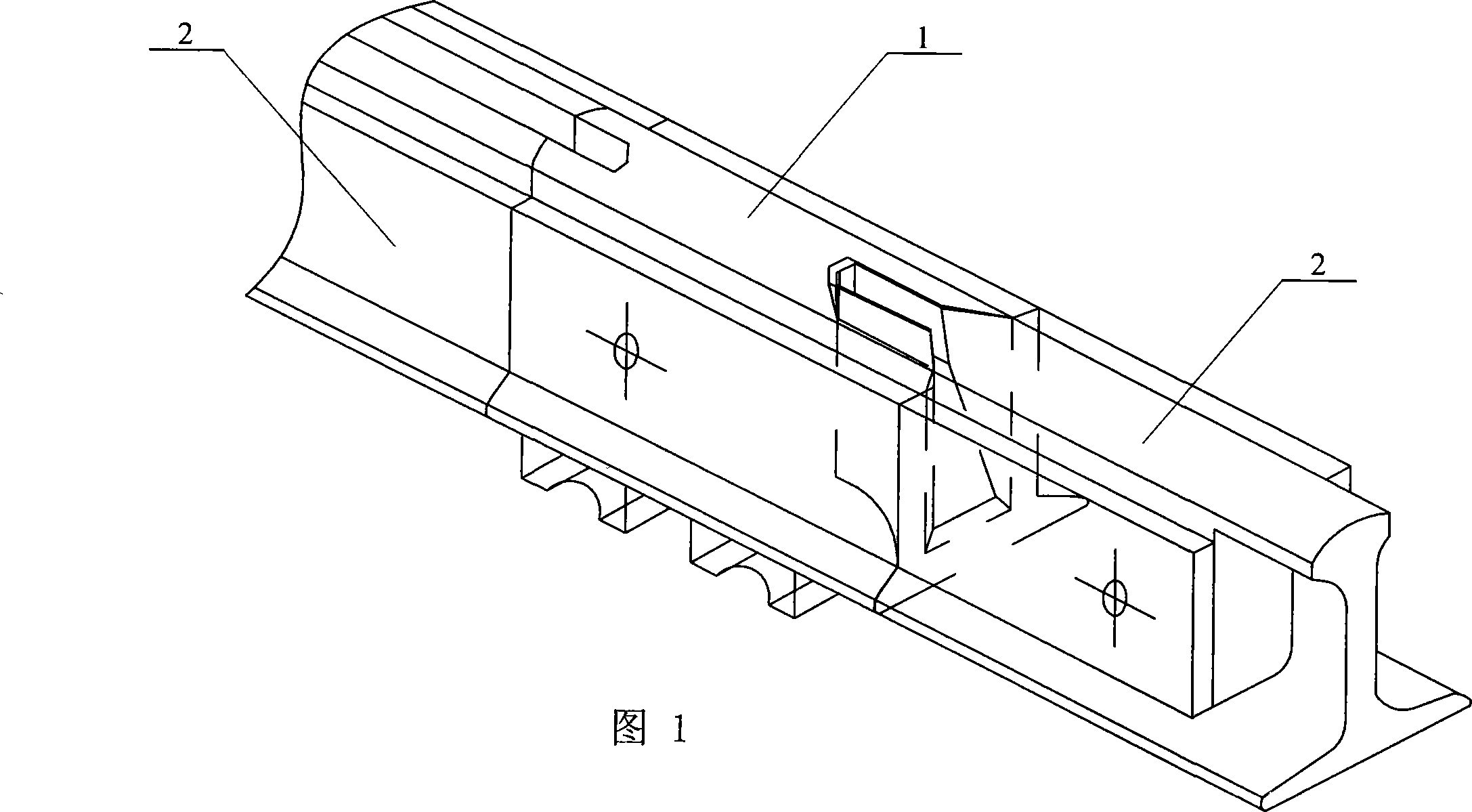
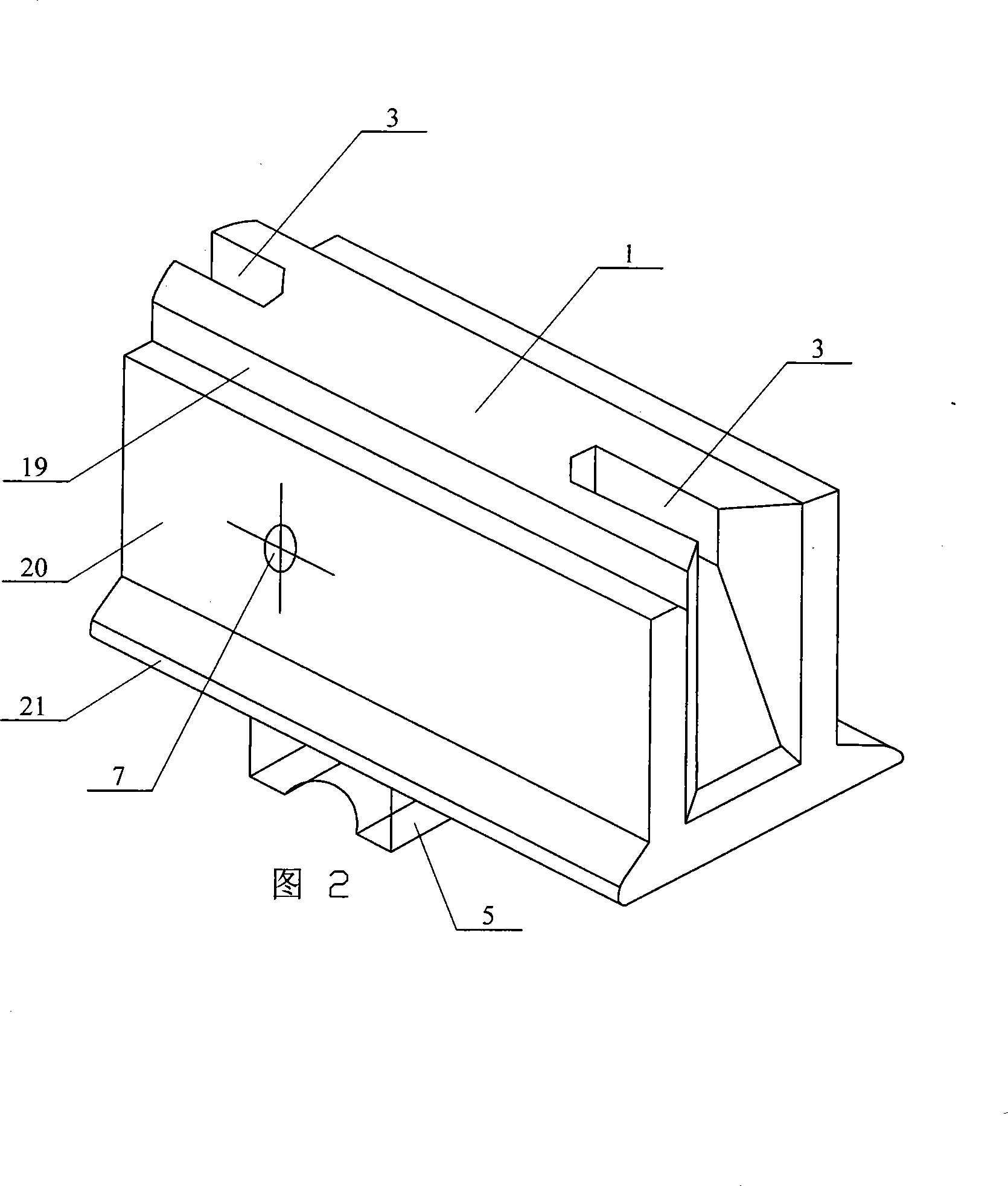
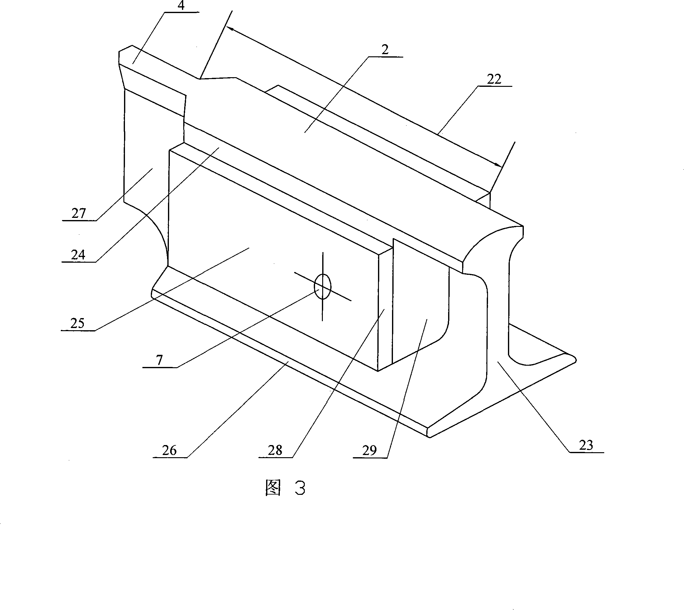
[0007] Specific embodiment 1: This embodiment is described with reference to Figures 1 to 4. This embodiment is composed of a static rail 1 and a moving rail 2; The connecting groove 3, and the connecting groove 3 is set on the central axis of the static rail 1, and one end of the moving rail 2 is provided with a connecting tenon 4 matching with the connecting groove 3, and the connecting tenon 3 is arranged on the moving On the central axis of the rail 2, the insertion slots 3 at both ends of the static rail 1 are equipped with a plug-in tenon 4 that transitions dynamically with it, and the cross-section shape of the other end of the moving rail 2 is the same as that of the 60 rail. At least two bases 5 are arranged on the lower end surface of the rail 1 along the length direction, the middle part of the lower end surface of the base 5 is a circular arc surface 6, and the corresponding positions on the static rail 1 and the moving rail 2 are horizontally provided with wire con...

specific Embodiment approach 2

[0008] Specific embodiment two: This embodiment is described in conjunction with Fig. 2, Fig. 4, and Fig. 6. The insertion groove 3 of this embodiment is composed of an inner end face 8, a front side, a rear side, a bottom end face 11, and an outer slope 12; The inner end surface 8 of the connection groove 3 is a V-shaped end surface, and the front side of the insertion groove 3 is composed of a first vertical surface 13, a first inclined surface 14 and a second inclined surface 15. The inner end of the first vertical surface 13 and the The inner end of the first slope 14 is connected with the front end of the V-shaped end face, the lower end of the first vertical surface 13 is connected with the upper end of the first slope 14, the lower end of the first slope 14 is connected with the front end of the bottom end surface 11, and the first vertical The outer end of the surface 13 and the outer end of the first inclined plane 14 are respectively connected with the inner end of th...

specific Embodiment approach 3

[0009] Specific Embodiment Three: This embodiment is described in conjunction with FIG. 5 . The distance H1 between the first vertical surface 13 and the second vertical surface 16 of the insertion groove 3 of this embodiment is 30mm, and the bottom end surface of the insertion groove 3 The width W1 of 11 is 50 mm. Such setting has the advantage of good connection stability. Other components and connections are the same as those in the second embodiment.


PUM

PropertyMeasurementUnit
Widthaaaaaaaaaa
Lengthaaaaaaaaaa
Lengthaaaaaaaaaa

Abstract

A plug-in steel rail joint connector with no buttcover plate of the invention relates to a steel rail joint connector, which aims at the problems of the buttcover plate connection type that the buttcover plate steel rail bolt holes can be easily cracked, the steel rail joint can be easily worn out, damaged, overlapped, collapsed and peeled off; and aims at the problems of large assembly work volume, bad weight-bearing and deformation ability of the joints of the vibration damping clampboard connection type and the symmetric inclined plane or inclined trapezohedron connection type with steel rail joint clampboards. Both ends of a static rail (1) of the invention are symmetrically provided with plug-in grooves (3), one end of a moving rail (2) is provided with a plug-in rod (4), the shape of the other end of the moving rail is same with the section shape of a rail 60, plug-in grooves of two ends of the static rail (1) is internally provided with the plug-in rod (4) which is movably fit with the plug-in groove in transition, the lower end surface of the static rail (1) is provided with a base (5), and the relative positions of the static and moving rails are provided with conduction wires connection holes (7). The connector of the invention has strong weight-bearing ability, small work volume of adjusting and maintaining and good vibration damping ability, and is most suitable for high-speed railways, urban rails, subways, tunnels, bridges and cargo-passenger stations.

Description

technical field [0001] The invention relates to a rail joint connector. Background technique [0002] At present, the connection of railway rail joints at home and abroad is mainly in the form of fishplate connection. In recent years, there are also forms of vibration-damping splint connection and symmetrical inclined plane or symmetrical inclined plane with rail joint splint connection. The use of fishplates to connect rail joints has the following problems: 1. There are cracks in the rail bolt holes of fishplates. From the initiation of cracks, to the expansion and even fracture, it is caused by the fatigue damage of tens of thousands of impact loadings of rolling stock. Especially after the railway speed-up and heavy load, this situation is more serious. According to the statistics of the number of cracks in rail screw holes after the operation of electrified heavy-duty combined trains by the relevant railway departments, through the analysis of statistical data for four...

Claims


Application Information

Patent Timeline
IPC IPC(8): E01B11/26
Inventor 陈力求
Owner 陈力求
Why Eureka
Try Eureka