

Traffic flow multiplication method for diversiform traffic light crossing
A technology of intersections and traffic flow, applied in the directions of roads, roads, buildings, etc., can solve the problems of road utilization coefficient falling to 0, low efficiency, etc., and achieve the effect of improving road utilization coefficient
- Summary
- Abstract
- Description
- Claims
- Application Information
AI Technical Summary
Problems solved by technology
Method used
Image

Examples
Embodiment 1
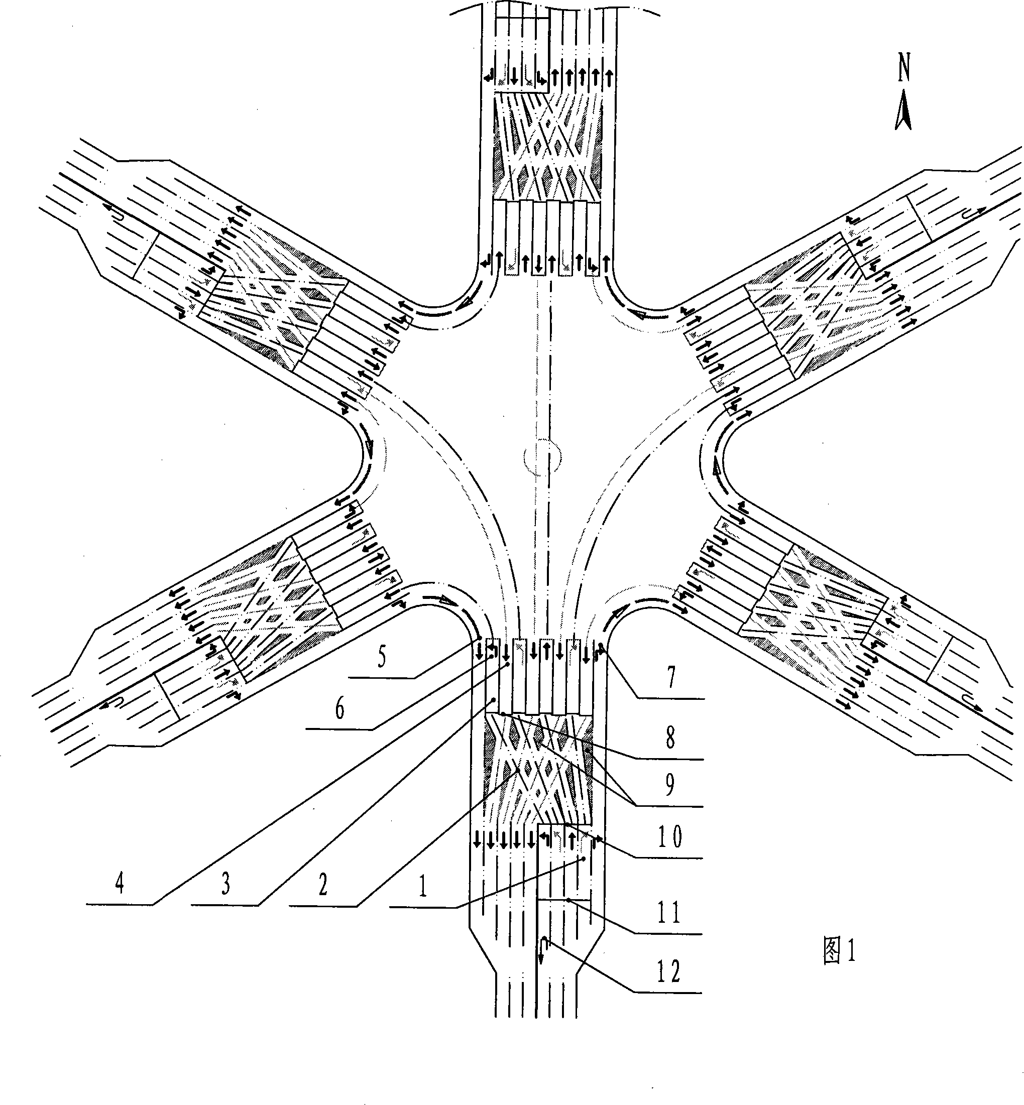
[0030] Embodiment 1, the embodiment of the intersection of six roads, referring to Fig. 1, each arterial road all is two-way 6 lanes.
[0031] The basic characteristics of the intersection: because each intersection has 5 pairs of vehicles to come and go, for this reason, the number of lane groups with different orientations near the intersection should be expanded to 10 groups. Each group can be one lane or multiple lanes. Take the South intersection as an example to illustrate the main structure:
[0032] A, except for the right-turning lane [group] on the far right, the waiting areas of different directional lanes are moved back a certain distance [such as 50 to 200m] from the original uplink intersection to form the first waiting area (1). The left field of the area (" is all downlink lanes. There are 4 groups of lane groups with different driving directions in the area (1). Each group only takes 1 lane in Fig. 1. From left to right, the ordering of different directional ...
Embodiment 2
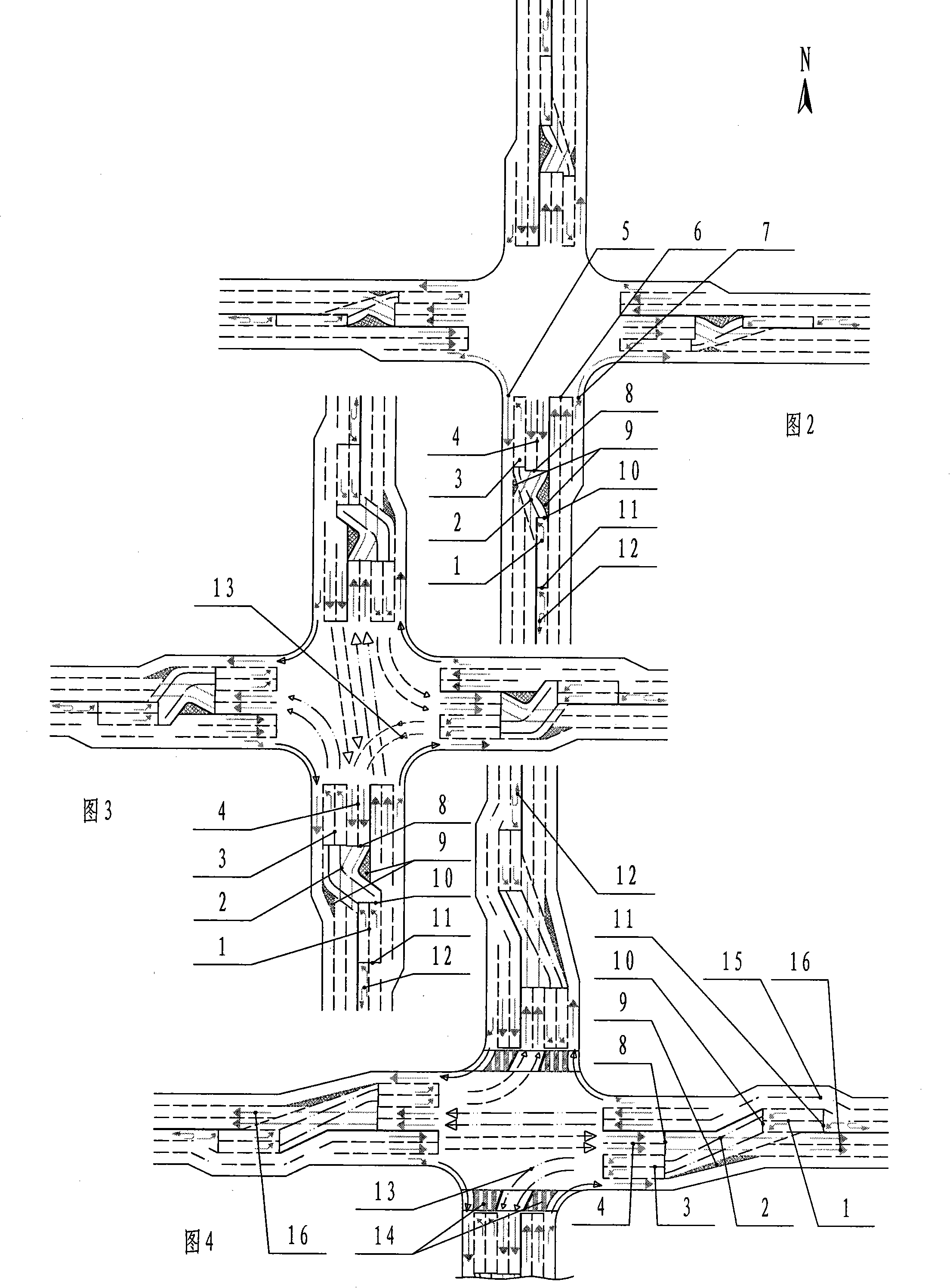
[0048] Embodiment 2, with reference to FIG. 2, introduces the basic features of the intersection of the present invention.
[0049] Each intersection has three directions of traffic. Therefore, at each intersection of the intersection, there are 6 lane groups for directional entry and exit. Corresponding parts in the figure are marked with the same symbols as in Fig. 1 . The traffic flow structure of its driving is greatly simplified compared with the six-way intersection. In the present invention, the second transition area (3) is also the second waiting area.
[0050] Take the north-south intersection [or east-west intersection] as an example, because the traffic flow at the north-south intersection [or east-west intersection] can turn right, go straight and turn left at the same time without conflict; is in release state. After the above design is further evolved, the plane intersection can obtain the maximum number of traffic lanes.
[0051] Combined with Fig. 3, the ...
Embodiment 3
[0060] Embodiment 3, as shown in Figure 3, in order to improve the average vehicle speed of vehicles in the downlink area, the plane layout of the crossroads can be changed locally asymmetrically: the first waiting area (1) and its right adjacent lanes (15 ) are all translated to the right, so that the traffic flow (16) descending from the third transition zone (4) exit can run straight.
[0061] About zebra crossing:
[0062] Referring to the crossroad of Fig. 4, the zebra crossing (14) of segmental release can be set at the intersection parallel with the straight traffic flow. When the corresponding straight traffic flow is released, the section of the zebra crossing (14) can be opened. Pedestrians and non-motor vehicles stop at the boundary of the adjacent left-turn traffic flow (13) lane. After the traffic flow (13) passes through, pedestrians and non-motor vehicles are allowed to complete crossing; thus, the time for pedestrians to cross the street can be shortened, and...
PUM
 Abstract
Description
Claims
Application Information