Hollow glass curtain wall
A glass curtain wall and hollow technology, applied to walls, building components, buildings, etc., can solve problems such as waste, no formula, and potential safety hazards
- Summary
- Abstract
- Description
- Claims
- Application Information
AI Technical Summary
Problems solved by technology
Method used
Image
Examples
Embodiment 1
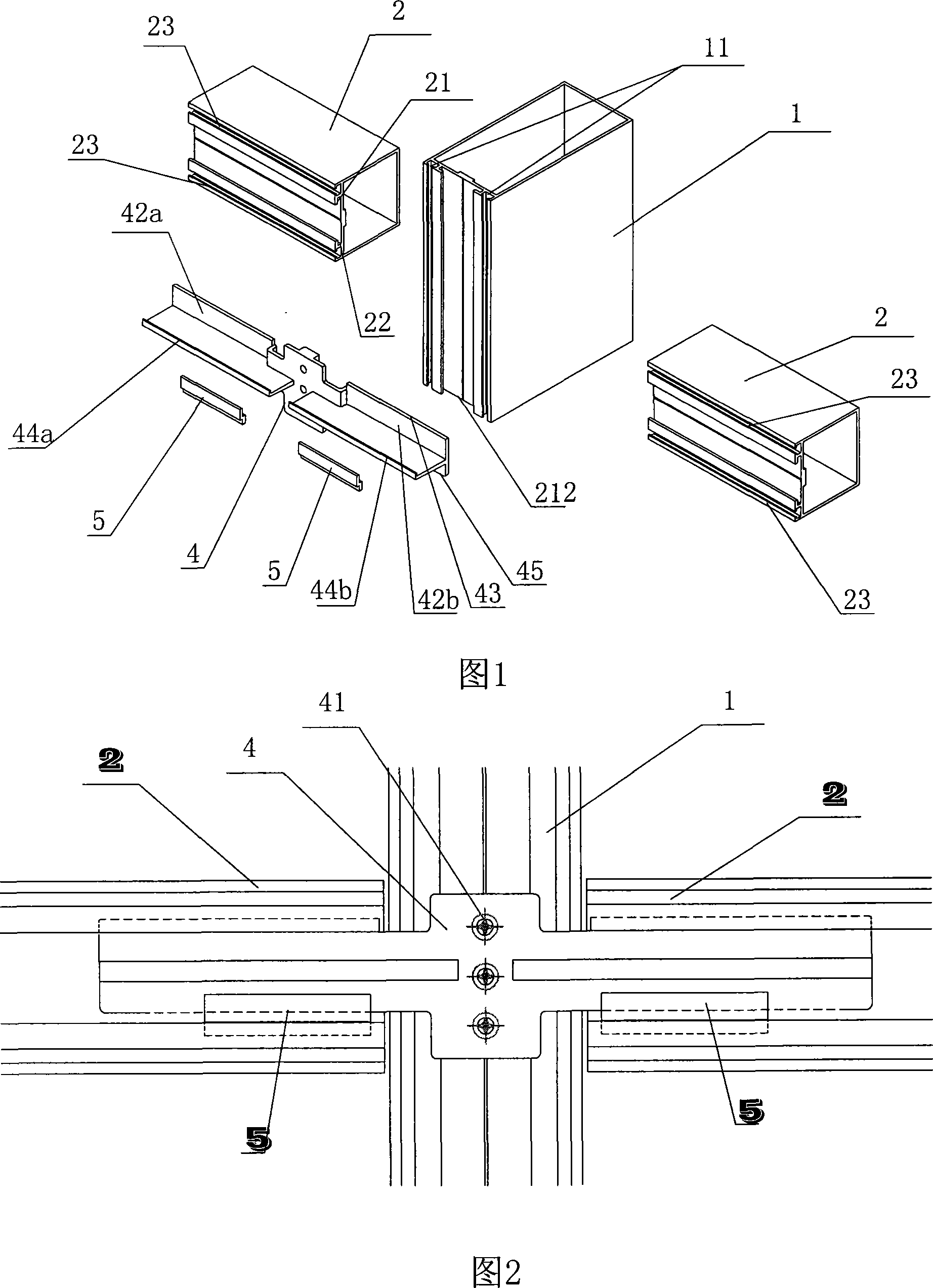
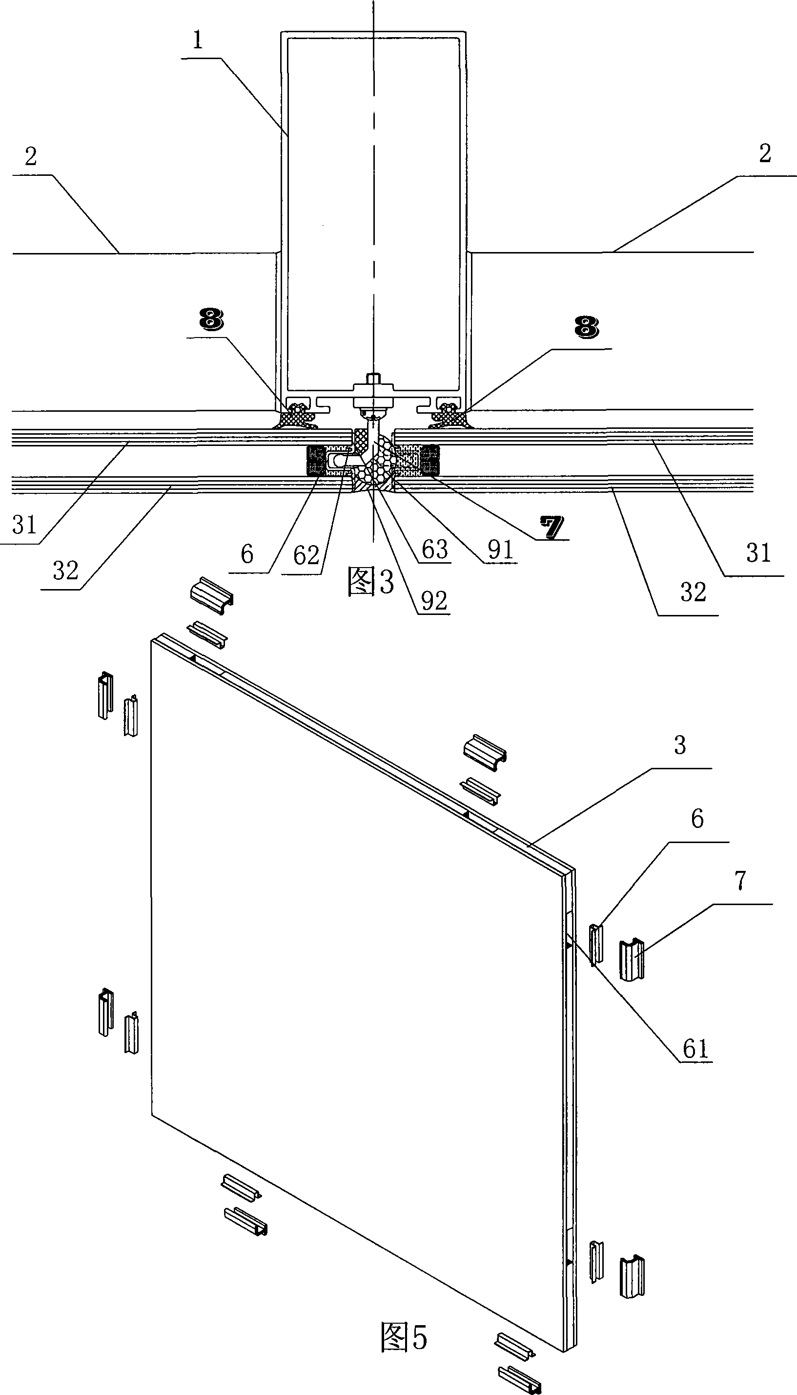
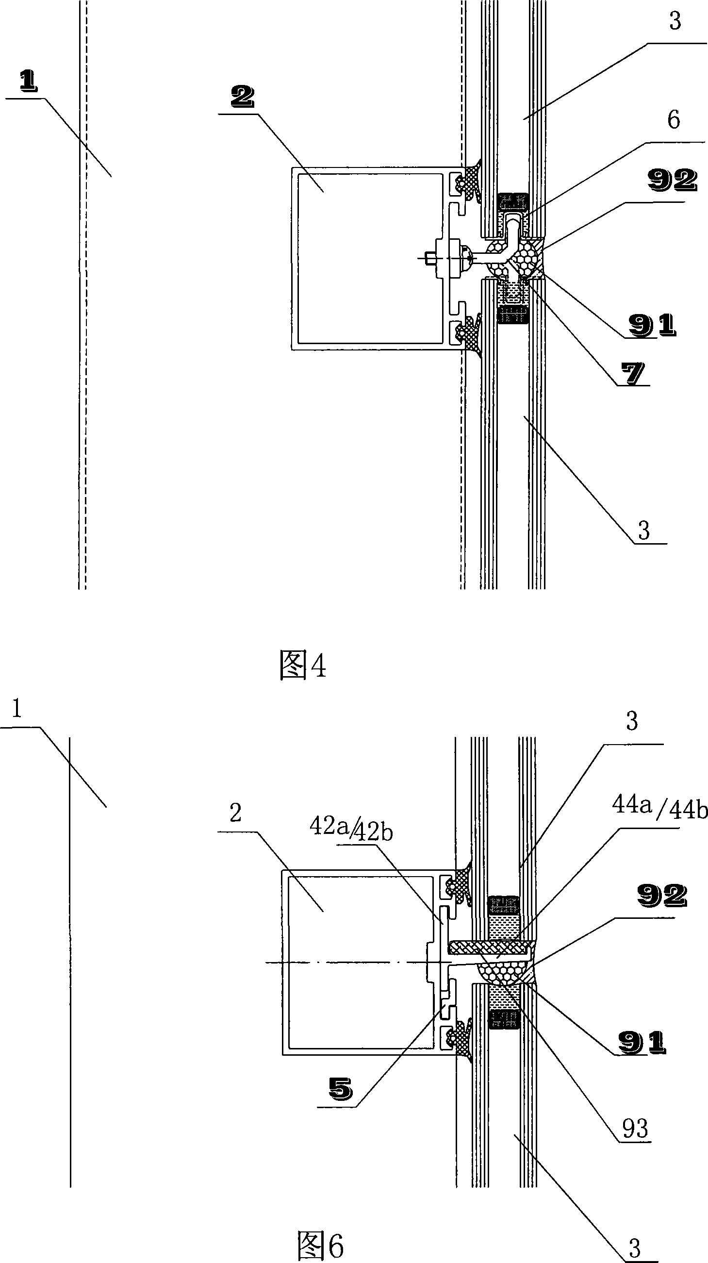
[0016] Embodiment 1, embodiment of hidden frame glass curtain wall, refer to accompanying drawings 1-6.
[0017] The present invention includes a column 1, a beam 2, and a hollow glass plate 3. The hollow glass plate includes an inner glass plate 31 and an outer glass plate 32. The hollow glass curtain wall is provided with a multifunctional connector 4.
[0018] The multi-functional connector is installed on the column by screws 41, the multi-functional connector has wing plates 42a, 42b connected to the beams on both sides of the column, and the front of the beam is provided with the upper edge 43 of the wing. Matching groove 21, the crossbeam is hung on the wing plate, and the multifunctional connector is also provided with supporting plates 44a, 44b of the hollow glass plates on the wing plate, and the adjacent bottom corners of the adjacent hollow glass plates arranged side by side supported on the pallet.
[0019] The present invention is also provided with a pin piece ...
Embodiment 2
[0026] Embodiment 2, embodiment of exposed frame glass curtain wall, refer to accompanying drawings 1, 2, 7, 8, 9. The keel system of this embodiment adopts the keel system of the hidden frame glass curtain wall of Embodiment 1, and the same reference numerals in Figures 7, 8, and 9 as those of Embodiment 1 represent the same meanings.
[0027] As shown in the figure, this embodiment establishes an exposed frame glass curtain wall system on the basis of the above-mentioned keel system, which will be described in detail below.
[0028] It is provided with a pressure plate 260 for the hollow glass plate, the pin slot 22 on the beam, the groove 21 that is hooked and matched with the edge of the wing plate, and the front of the beam between the above two grooves is formed as a clamping groove for the pressure plate mounting part 270 , the front of the column is also provided with a pressure plate mounting part slot 212 of the same shape as the pressure plate mounting part slot on ...
PUM
 Abstract
Description
Claims
Application Information
 - R&D
- Intellectual Property
- Life Sciences
- Materials
- Tech Scout
- Unparalleled Data Quality
- Higher Quality Content
- 60% Fewer Hallucinations
Browse by: Latest US Patents, China's latest patents, Technical Efficacy Thesaurus, Application Domain, Technology Topic, Popular Technical Reports.
© 2025 PatSnap. All rights reserved.Legal|Privacy policy|Modern Slavery Act Transparency Statement|Sitemap|About US| Contact US: help@patsnap.com


