Sliding block rotor pump

A rotor pump and slider type technology, which is used in rotary piston pumps, pumps, and rotary piston machines, etc., can solve the problems of short service life of rotor pumps, unstable working conditions, and low working efficiency of slider pumps. Small fluid pulsation, long service life and low working noise

Inactive Publication Date: 2008-01-23
CHONGQING JINYANG REFREGRATION EQUIP MFG
View PDF3 Cites 0 Cited by
  • Summary
  • Abstract
  • Description
  • Claims
  • Application Information

AI Technical Summary

Problems solved by technology

[0003] The purpose of the present invention is to retain the performance advantages of the rotor pump and the slider pump, and overcome the shortcomings of the rotor pump's short service life and the slider pump's relatively low working efficiency, relatively large noise, large fluid pulsation, unstable working state, and small pressure ratio , to improve the existing rotor pump, to provide a new slider type rotor booster pump

Method used


Image

  • Sliding block rotor pump
  • Sliding block rotor pump
  • Sliding block rotor pump

Examples


Embodiment 1

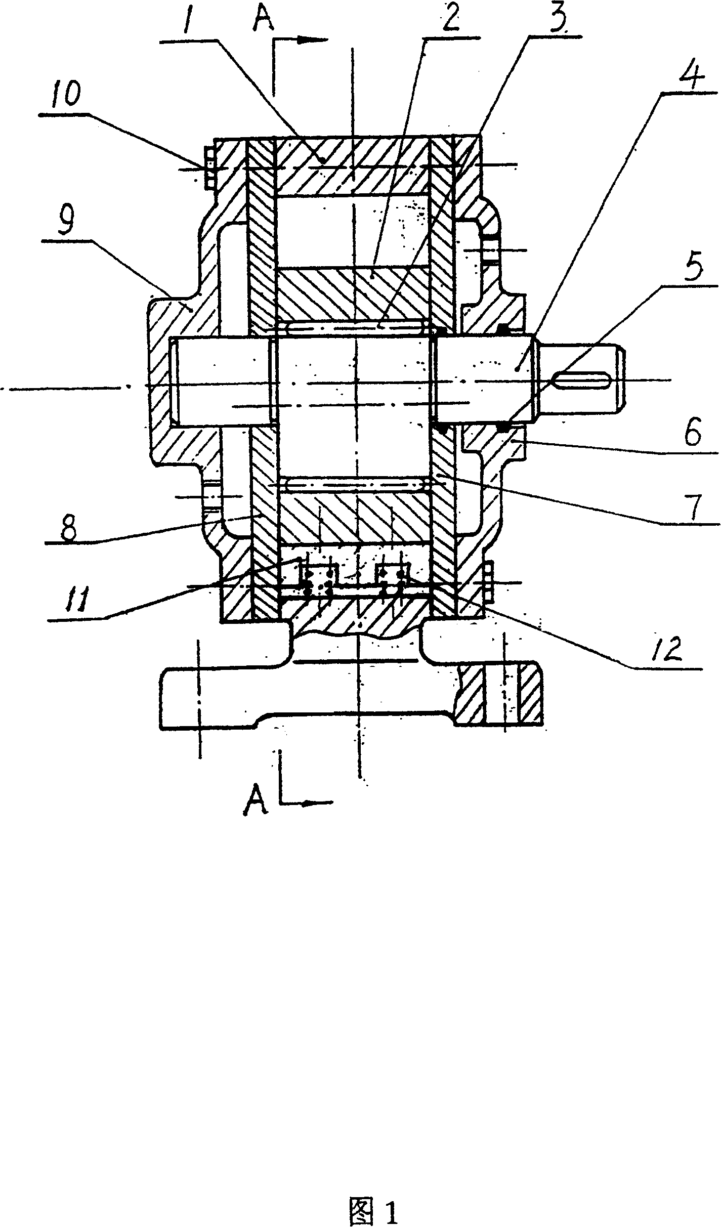
[0029] Embodiment 1 is a slider type rotor pump composed of a quadrilateral rotor 2 and a three-arc stator 1 composed of three-segment curves with an inner cavity that is equally divided. The pump consists of a three-arc stator 1, a quadrilateral rotor 2, and rolling elements 3 , eccentric shaft 4, front distribution plate 7, rear distribution plate 8, front inlet flow cover 6, rear end cover 9, a quadrilateral rotor 2 is installed in the inner cavity of the three-arc stator 1, and a quadrilateral rotor 2 is installed in the inner hole of the quadrilateral rotor 2 Install a number of rolling elements 3 and eccentric shaft 4, put the central circular holes of the front distribution plate 7 and the rear distribution plate 8 into the two ends of the eccentric shaft 4 respectively, and place them on the two ends of the three-arc stator 1. The central round holes of the front inlet flow cover 6 and the rear end cover 9 are inserted into the two ends of the eccentric shaft 4 respecti...

Embodiment 2

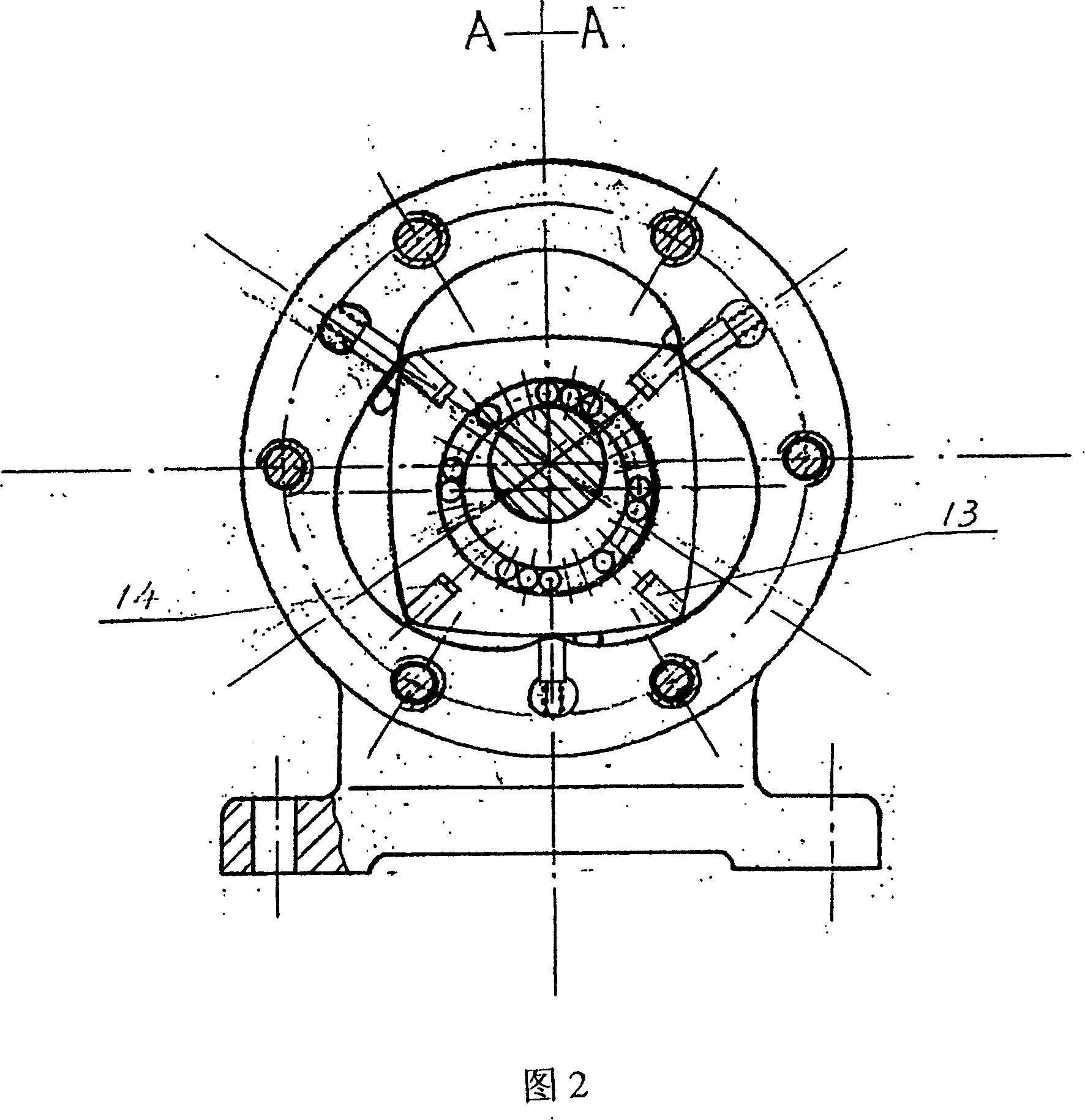
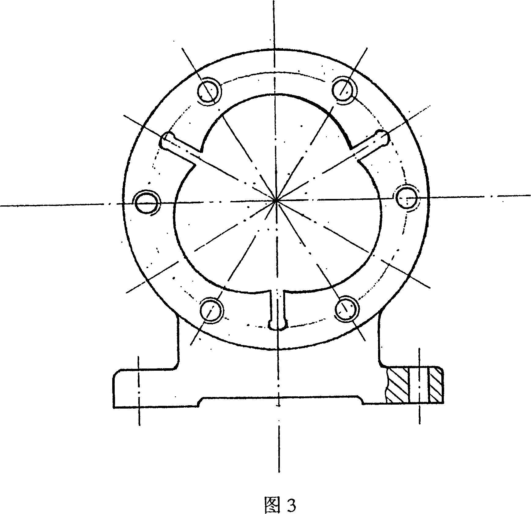
[0035] Embodiment 2 is a slider-type rotor pump composed of a triangular rotor 15 and an 8-shaped stator 16 formed by two curves in the inner cavity. Above the three apex sections of the triangular rotor 15, a through slot is opened along the axial direction. , and have a certain depth in the radial direction. A rotor slider 13 with the same width as the rotor in the axial direction is placed in each of the three through grooves. A shrapnel 14 is installed between the bottom of each slider and the bottom of the through groove, so that The slider can be freely expanded and contracted in the radial direction: above the two apex sections of the stator, a through slot is opened along the axial direction, and has a certain depth in the radial direction, and a slot along the axial direction and Stator sliders 11 with the same width as the stator, springs 12 are respectively installed between the bottom of each slider and the bottom of the through groove, so that the slider can freely...


PUM


Abstract

The invention relates to a slider rotor pump that a through groove is set at the top of every apex angle section along the axis direction. Rotator slider that has the same width as the rotor is located in the through groove, and the slider could freely extend along the radial direction. A through groove is set at the top of every apex angle section of stator along the axis direction and locating a stator slider that has the same width as the stator in the through groove that can make the slider freely extend along the radial direction. The invention has the advantage of high mechanism efficiency of rotor pump, high volumetric efficiency, low liquid impulse, low working noise and large pressure ratio, and moving contact that has no clearance and long useful life. It can be broadly used in oil pump, water pump, gas compressor, refrigeration compressor, vacuum pump, etc.

Description

technical field [0001] The invention relates to a pump for fluid delivery and pressurization, belonging to a fluid mechanical device. Background technique [0002] At present, the pumps used for fluid delivery and pressurization mainly include rotor type, slider type, plunger type, screw type, scroll type, etc. The rotor type booster pump has the advantages of high mechanical efficiency, high volumetric efficiency, small fluid pulsation, low working noise, and large pressure ratio. A very high running accuracy is guaranteed, so a sufficiently long service life cannot be obtained. The slider type booster pump can maintain gap-free motion contact and has the function of contact pair wear compensation, so that it can obtain a longer service life, but it also has relatively low working efficiency, relatively large noise, large fluid pulsation, and insufficient working conditions Stable, small pressure ratio and other shortcomings. In the prior art, there is also a booster pum...

Claims


Application Information

Patent Timeline
Patent Type & Authority Patents(China)
IPC IPC(8): F04C2/356F04C18/356
Inventor 王剑李亚平吴乃决
Owner CHONGQING JINYANG REFREGRATION EQUIP MFG
Why Eureka
Try Eureka