Attached lifting scaffold trolley type inclining-proof device and method of use thereof

A technology of attaching lifting and scaffolding, which is applied to the scaffolding of house structure support, house structure support, house structure support, etc. It can solve the problems of easy slipping, low safety factor, and unstable fastener connection, etc., so as to ensure the installation and use effect , Enhanced anti-shear ability, convenient relative movement effect

Active Publication Date: 2008-07-09
湖南省第五工程有限公司 +1
View PDF0 Cites 11 Cited by
  • Summary
  • Abstract
  • Description
  • Claims
  • Application Information

AI Technical Summary

Problems solved by technology

The anti-overturning function of the attached lifting scaffold is an important safety indicator. At present, the anti-tilting function of the external scaffolding is to use steel pipe guide rails to prevent the attached lifting scaffold from overturning during the lifting process. To prevent the frame body from overturning when it is in a static state, the anti-tilt track used is an ordinary steel pipe, which is installed in parallel with the inner pole on the main frame attached to the lifting scaffold, and the wall parts are fasteners and side beams or shear force of the building. Wall connection is generally required to be installed on each floor. The connection method is to embed screw holes in the side beam or shear wall, and then use the wall screw to connect with the anti-tilt device after the formwork is removed. The convex surface, the fastener and its contact area are small, the fastener’s anti-slip ability is relatively low, and it is prone to slipping, so the anti-rolling effect of this structure is limited. In addition, the quality of the fastener itself is uneven, and the safety factor is low. Unstable connection of fasteners, artificial removal of the outer frame caused the overturning phenomenon, and safety accidents occurred
Its use places are also subject to certain restrictions, and may not be used in the following buildings: such as buildings with large open spaces, buildings with cylindrical structures with full-page shear walls, special-shaped buildings, chimneys, water towers and other high-rise buildings
If the conventional method is used to erect the connecting wall poles, it often cannot meet the two-step and three-span connection requirements required by the code. Most of these buildings are high-rise buildings. It is required to pre-embed steel pipes or iron parts on the wall shears, which will inevitably cause waste of resources and increase costs, and is not economically feasible.
[0003] Especially during the lifting process of the attached lifting scaffold, the steel pipe guide rail can not restrict the front, rear, left, and right swing of the attached lifting scaffold while the steel pipe guide rail can guide the lifting of the attached lifting scaffold, which cannot meet the requirements for safe operation of the lifting. prohibit

Method used


Image

  • Attached lifting scaffold trolley type inclining-proof device and method of use thereof
  • Attached lifting scaffold trolley type inclining-proof device and method of use thereof
  • Attached lifting scaffold trolley type inclining-proof device and method of use thereof

Examples


Embodiment 1

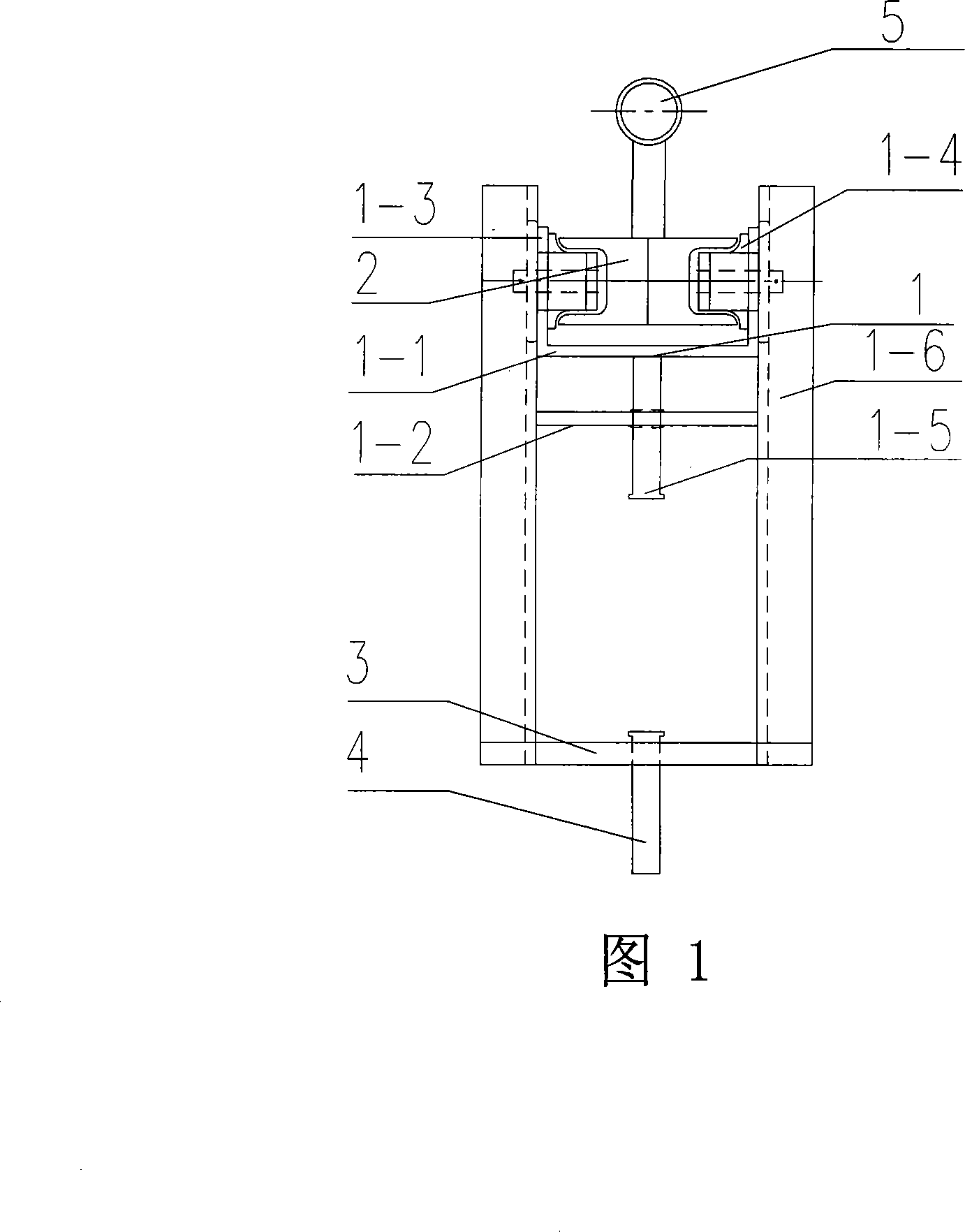
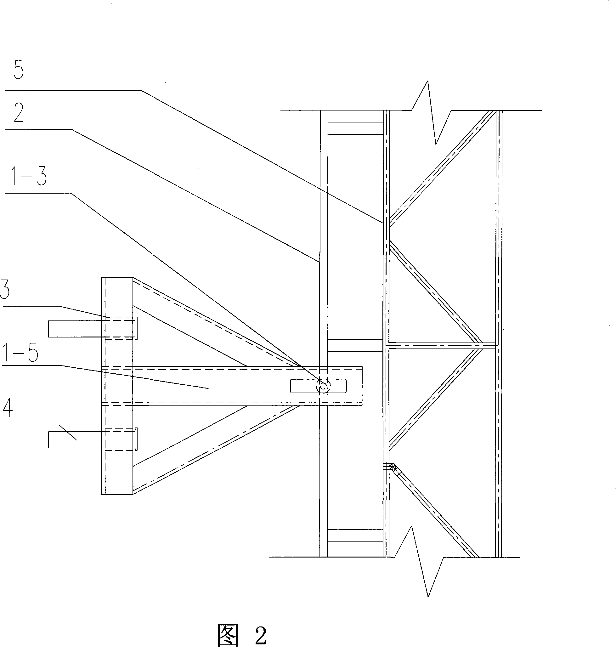
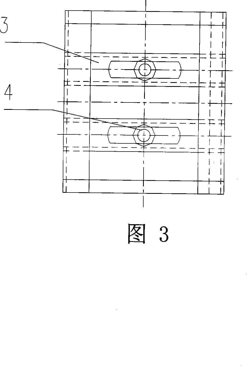
[0029] Example 1: An engineering company constructs a building with a total of 34 floors, the standard floor height is 3.00m, and the roof height is 109.72m, all of which adopt frame shear wall structure. Standard floor (7.22m to 109.72m) floors use attached lifting scaffold construction, all adopt the anti-rolling device of the present invention. Its structure is shown in Figures 1-3: the anti-tilt track 2 is No. 10 I-beam, and the structure of the anti-tilt component 1 is: two M24 wall-through bolts 4 pass through the wall and will be attached to the wall and the building The object connection plate 3 is fixed, and is fixed with the support 1-6 of two horizontal overhangs on the building connection plate 3, is respectively placed on both sides of the anti-tilt track 2, and the support 1-6 is provided with a horizontal groove, and the two support 1 An anti-tilt structure box 1-1 is erected between the -6 and the anti-tilt rail 2 for relative movement up and down, and a pair o...

Embodiment 2

[0045] An engineering company constructs commercial housing. The project is a frame shear wall structure with a construction area of ​​56,000 square meters and a roof height of 89m. The 1-3 floors are podium buildings, 26+1 floors above ground, 1 floor underground, and 4-26 floors of standard floors. From the standard floor 4-26, use the attached lifting scaffold for construction. The shape of the building is relatively complicated, and there are arcs, corners, balconies, and pick-up boards around the building, which brings certain difficulties to the construction of the outer frame. At the arc, the bottom of the anti-tilt component needs to be padded with gaskets, and the connecting steel column is added to the pick plate to make the connection between the frame body and the anti-tilt component have sufficient rigidity to meet the construction requirements.

[0046] The structure of the anti-tilt component is: 6 M24 wall-through bolts 4 pass through the wall to fix the wall ...


PUM


Abstract

The invention discloses a pulley-type inclination-preventing device for an attached lifting scaffold and a method for using, the inclination-preventing device comprises a vertical bar-shaped inclination-preventing rail with a longitudinal inner concave and an inclination-preventing component, the structure of the inclination-preventing component is that 2-6 typed wall bolts are penetrated through wall and fix a connection board which is clung on wall surface, two supporting stands which are horizontally extended outwards and respectively arranged on the inclination-preventing rail are fixed on the connection board, an inclination-preventing conformation box which only does up and down movements with the inclination-preventing rail is erected between the two supporting stands, the inclination-preventing conformation box is composed of a pulley which is inserted into the inner concave of the inclination-preventing rail and the inclination-preventing rail which are connected, and the pulley is fixed on the inclination-preventing conformation box which surrounds the inclination-preventing rail. The invention has the advantages of excellent inclination-preventing property, safety and reliability, convenient disassembly and low component cost and can be used repeatedly, and the method for using which is disclosed can realize better safety of the attached lifting scaffold and can satisfy safe operational requirements of the attached lifting scaffold.

Description

technical field [0001] The invention relates to building construction equipment and its use method, in particular to an anti-tilt device attached to a lifting scaffold and its use method. Background technique [0002] Attached lifting scaffolding is a tool-type scaffolding that is divided into spans and does not fall to the ground. It is generally 6 to 8 steps, and it is attached to the outer wall of the building to meet the requirements of structural engineering and exterior wall decoration construction for the segmented construction of scaffolding. , has been widely used in high-rise building construction. Its lifting movement is realized by lifting and lowering the movable frame and the anti-rolling device through the electric hoist. When the scaffold is in working condition, the anti-tilt device is relatively fixed to the wall; when the scaffold needs to be raised and lowered, the electric hoist is used to lift the frame body, and the load-bearing diagonal rods and anti...

Claims


Application Information

Patent Timeline
Patent Type & Authority Applications(China)
IPC IPC(8): E04G3/28
Inventor 钟祝平郭秋菊王春茂朱卫东胡志高郑明勇
Owner 湖南省第五工程有限公司
Why Eureka
Try Eureka