Plate-type friction-changing damper

A variable friction and damper technology, which is applied to friction dampers, building components, shockproof, etc., can solve the problems of complex devices and difficult implementation, and achieve the effect of easy material acquisition, low cost and stable performance

Inactive Publication Date: 2008-07-09
BEIJING UNIV OF TECH
View PDF1 Cites 29 Cited by
  • Summary
  • Abstract
  • Description
  • Claims
  • Application Information

AI Technical Summary

Problems solved by technology

In order to overcome this shortcoming of the constant friction damper, Li Hongnan and others invented a semi-active piezoelectric friction damper (CN 1594775A), which changes the friction force by changing the positive pressure, but the device is complicated and requires a certain amount of energy, which is difficult to implement

Method used


Image

  • Plate-type friction-changing damper
  • Plate-type friction-changing damper
  • Plate-type friction-changing damper

Examples


Embodiment 1

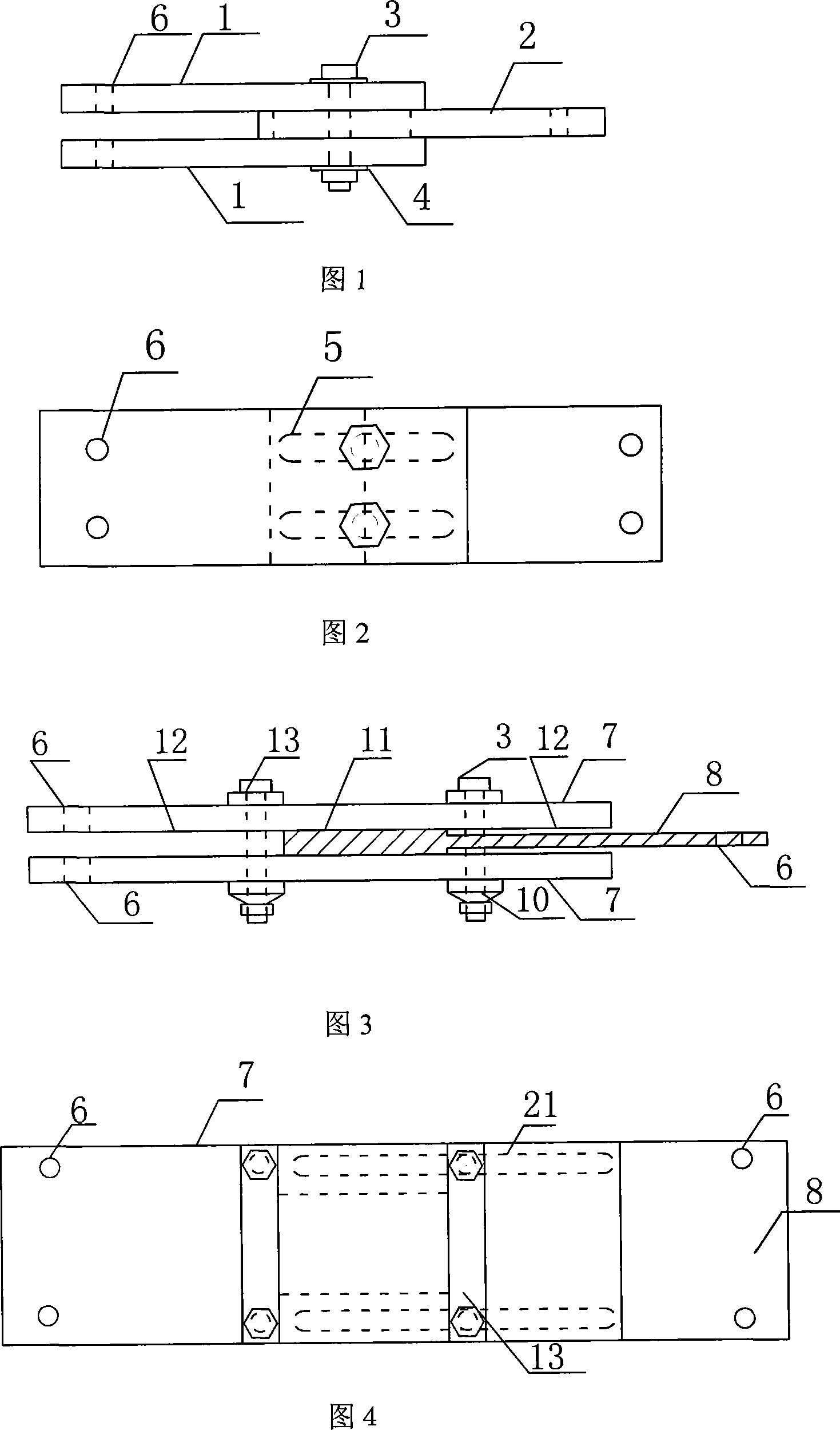
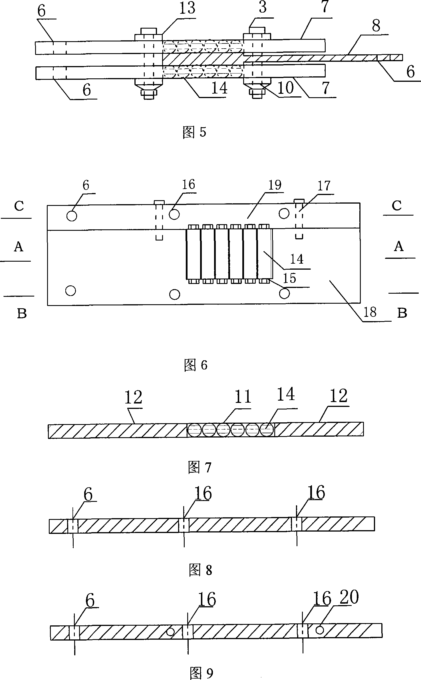
[0041] In this embodiment, the difference between the friction coefficients of the middle friction surface and the friction surfaces on both sides is realized by using the difference between the steel-steel rolling friction coefficient and the sliding friction coefficient. The structure of embodiment 1 is shown in Figure 5, mainly including cover plate 7, sliding plate 8, pre-tightening bolt 3, disc spring 10 and spacer 13, sliding plate 8 is located between two cover plates, slides relative to the cover plate; Tighten the bolt 3 to press the two cover plates to provide a positive pressure between the contact surface of the sliding plate 8 and the cover plate 7; the size of the positive pressure is controlled by changing the compression amount of the disc spring 10, and the spacer 13 enhances the rigidity of the cover plate The structure of the cover plate is as shown in Figures 6-9, consisting of steel plates 18, strip plates 19, rollers 14 and bearings 15, the bearings 15 are...

Embodiment 2

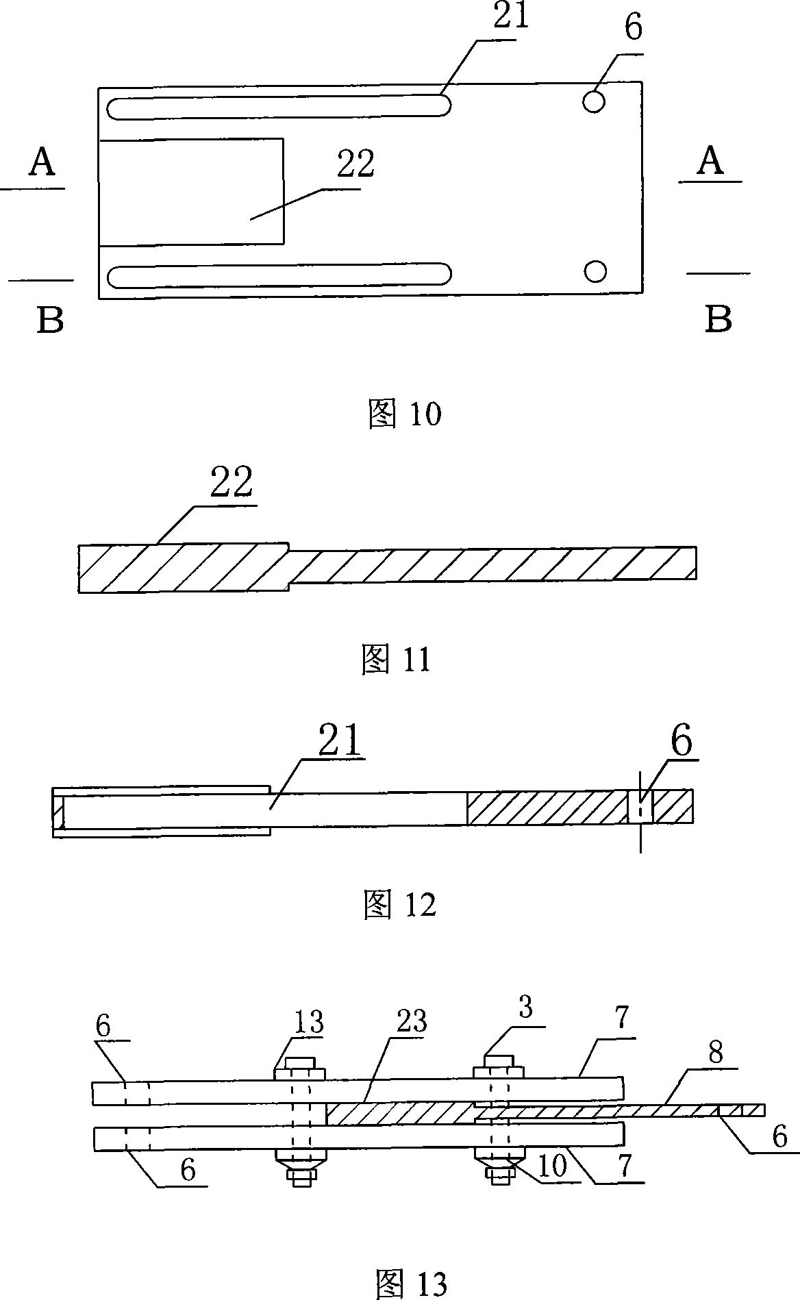
[0043]In this embodiment, the Teflon coating can greatly reduce the friction coefficient to realize the difference in the friction coefficient between the middle friction surface and the friction surfaces on both sides. Embodiment 2, as shown in Figure 13, mainly includes a cover plate 7, a sliding plate 8, a pre-tightening bolt 3 and a disc spring 10. The sliding plate 8 is located between the cover plates and slides relative to the cover plate; the high-strength pre-tightening bolt presses the cover plate , to provide a positive pressure between the sliding plate and the contact surface of the cover plate; the size of the positive pressure is controlled by changing the compression amount of the disc spring. The middle third of the friction surface of the cover plate 7 is plated with Teflon coating. Since the thickness of Teflon is only tens of microns, the local plating of Teflon on the steel plate will not cause the friction surface to be uneven. The structure of the slidin...


PUM


Abstract

The invention relates to a plate type variable friction damper, which is primarily used in the field of wind resistance and shock resistance of structures and equipments. The invention makes use of the variation of the friction factor of a friction surface to provide a linear damping variable friction damping device. The plate-type variable friction damper primarily consists of two cover boards, a sliding panel, a pre-tightening bolt, a disk spring and a packing strip. The friction surface of the cover board is divided into three equal parts; the friction factor between the middle friction surface and the friction surface of the sliding panel is smaller than the friction factors between the friction surfaces of the two parts on both sides and the friction surface of the sliding panel. The plate-type variable friction damper avoids the defects of high cost, being maintained intricately and oil leakiness of the traditional linear damping device, such as the oil damper, and overwhelms the problem that the constant friction damper can not keep the same control under different loads. The invention has simple structure, and is produced easily with low cost. The invention is applicable for both large structures and small structures and equipments, and is suitable to be promoted and used in the field of shock resistance of structures and equipments.

Description

technical field [0001] The invention relates to a plate type variable friction damper, which is mainly used in the fields of wind resistance and earthquake resistance of structures and equipment. It can also be used in conjunction with vibration isolation devices, TMD, etc. to improve its control effect. Background technique [0002] In order to reduce the wind vibration and earthquake response of structures and equipment, energy dissipation vibration damping devices can be arranged on structures and equipment to dissipate energy and achieve the purpose of reducing structural response. In the 30 years since Kelly et al. proposed the concept of energy dissipation vibration reduction in the early 1970s, a large number of energy dissipation vibration reduction devices have been developed. According to their energy dissipation mechanism, they can be divided into four categories: viscoelastic dampers, viscous dampers, metal dampers and friction dampers. Among them, the viscous ...

Claims


Application Information

Patent Timeline
Patent Type & Authority Applications(China)
IPC IPC(8): F16F7/08E04B1/98
Inventor 周锡元秦丽闫维明
Owner BEIJING UNIV OF TECH
Why Eureka
Try Eureka