Automobile air conditioner parallel flow evaporator

An automotive air-conditioning, parallel flow technology, applied in evaporator/condenser, space heating and ventilation details, household heating, etc. Effect

Inactive Publication Date: 2008-07-09
上海精励汽车科技有限公司
View PDF0 Cites 39 Cited by
  • Summary
  • Abstract
  • Description
  • Claims
  • Application Information

AI Technical Summary

Problems solved by technology

[0003] At present, the production technology and processing technology of parallel flow condensers for automobile air conditioners are relatively mature, but the mass production of parallel flow evaporators is still in the early stage, and there is a common problem of low production ef

Method used


Image

  • Automobile air conditioner parallel flow evaporator
  • Automobile air conditioner parallel flow evaporator

Examples


Embodiment Construction

[0028] Please refer to the attached drawings to further describe the present invention.

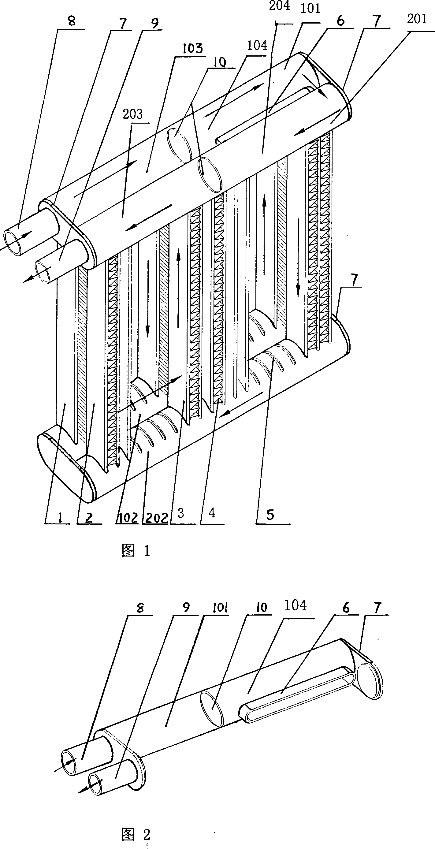
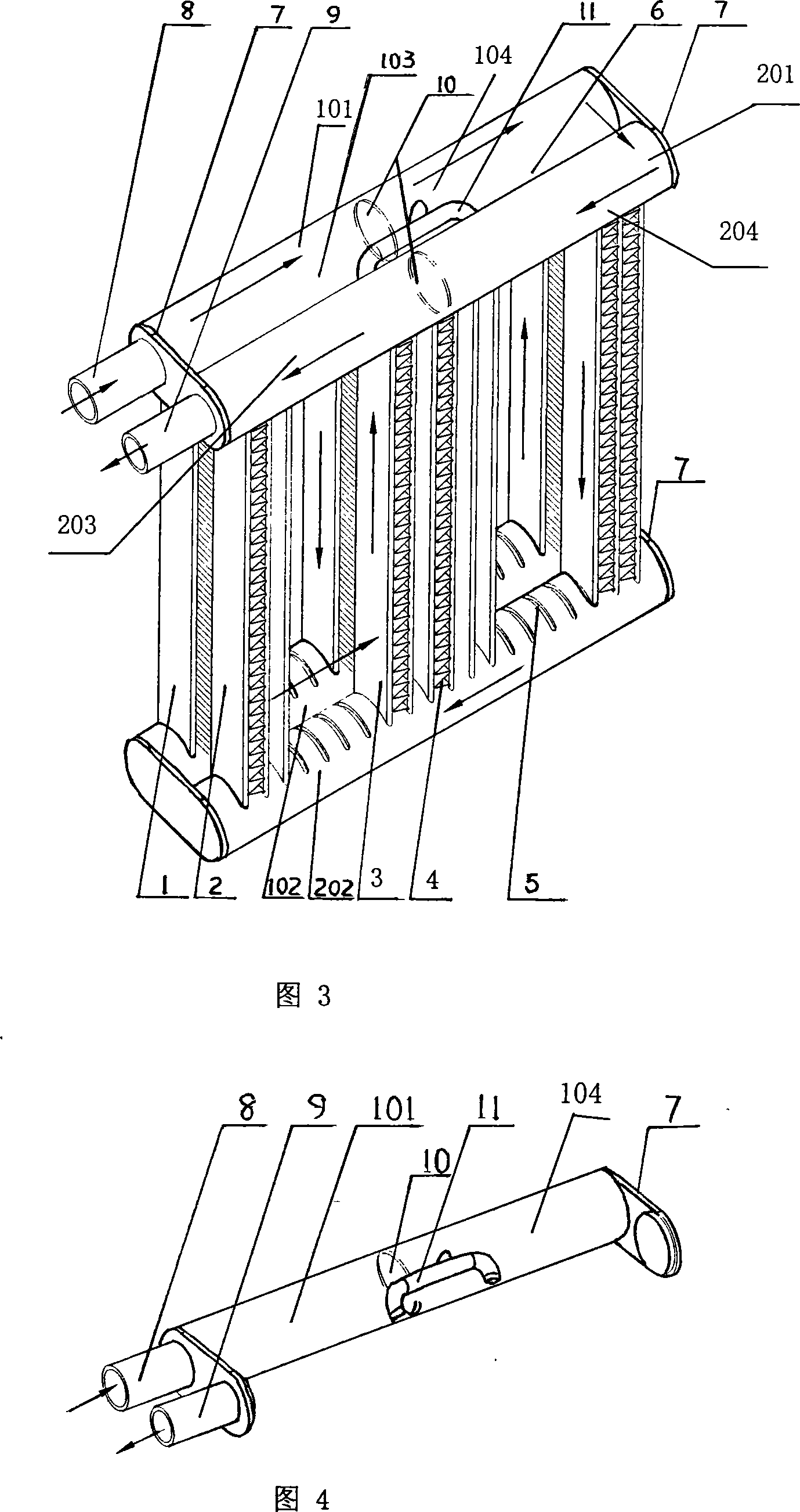
[0029] As shown in Figures 1 and 2, the present invention provides a parallel flow evaporator for automobile air conditioners. The parallel flow evaporator includes two sets of heat exchange units arranged in parallel before and after each set of heat exchange units include porous flat tubes 3 and fins. Sheet 4, upper header 101 / 201, lower header 102 / 202, header cover 7, partition 10, inlet pipe 8 and outlet pipe 9, said upper header 101 / 201, lower header The outside of the tube wall of the flow tube 102 / 202 is provided with a number of mounting holes 5 for inserting the porous flat tube 3, and the porous flat tube 3 is respectively inserted into the upper header 201 and the lower header 202 of the front row heat exchange unit 2. In the mounting holes 5, the porous flat tubes 3 are respectively inserted into the corresponding mounting holes 5 of the upper header 101 and the lower header 102 o...


PUM


Abstract

A parallel flow evaporator used with an automobile air-conditioning system comprises two groups of front and rear heat-exchange units in parallel arrangement and with the same structures. The two groups of heat-exchange units have the similar structure to the heat-exchange unit in the exiting parallel flow evaporator, so that the known techniques for assembling porous flat tubes and upper and lower collector tubes of the parallel flow evaporator can be used, and the upper collector tubes of the two groups of heat-exchange units are communicated with each other by flow-guide tubes or a gas/liquid separator. The invention has the advantages that the invention solves the problem that prior art has difficulties in assembling the porous flat tubes and the upper and lower collector tubes of the parallel flow evaporator and greatly increases the production efficiency; the gas/liquid separator for communicating the upper collector tubes of the two groups of front and rear heat-exchange units can discharge the gas-phase coolant produced inside the flat tubes of the rear heat-exchange units in time by the discharge chamber of the front heat-exchange units, thereby realizing the complete utilization of heat-exchange area of the flat tubes of the rear heat-exchange units and improving the heat-exchange capability of the parallel flow evaporator.

Description

Technical field [0001] The invention relates to an evaporator for automobile air conditioners, in particular to a parallel flow evaporator for automobile air conditioners. Background technique [0002] In order to improve the heat exchange efficiency of the evaporator for automobile air conditioners and reduce the space required for its installation, its structure has been developed from the finned tube type and the tube belt type to the laminated type. At present, the laminated evaporator has begun to be gradually changed in structure. Replaced by a compact parallel flow evaporator. The refrigerant side of the parallel flow evaporator adopts a porous flat tube with a small hydraulic diameter, and the air side adopts louvered fins with higher heat exchange performance, so that the heat exchange on the air side and the refrigerant side is enhanced, which is considered to be the best A promising high-efficiency and compact automotive air-conditioning evaporator. [0003] At present...

Claims


Application Information

Patent Timeline
IPC IPC(8): F24F13/30F25B39/02
Inventor 陈江平施骏业陈波刘婷婷
Owner 上海精励汽车科技有限公司
Why Eureka
Try Eureka