Elevator armored rope bending fatigue state experimental bench

A bending fatigue and wire rope technology, which is applied in the field of the bending fatigue state test bench for elevator wire ropes, can solve the problems of single function and complicated driving, and achieve the effect of flexible and convenient operation, simple and compact structure, and avoiding heavy operation.

Inactive Publication Date: 2008-07-09
SHANGHAI JIAO TONG UNIV
View PDF0 Cites 52 Cited by
  • Summary
  • Abstract
  • Description
  • Claims
  • Application Information

AI Technical Summary

Problems solved by technology

[0004] The present invention aims at the deficiencies of the above-mentioned prior art, and provides an elevator steel wire rope bending fatigue state test bench, which can simulate the specific structure of the actual elevator suspension system, and can be used for the bending fatigue state of the steel wire rope under various tensions and winding conditions. detection, to overcome the shortcomings of the existing steel wire rope bending fatigue test bench with complex drive and single function

Method used


Image

  • Elevator armored rope bending fatigue state experimental bench
  • Elevator armored rope bending fatigue state experimental bench
  • Elevator armored rope bending fatigue state experimental bench

Examples


Embodiment 1

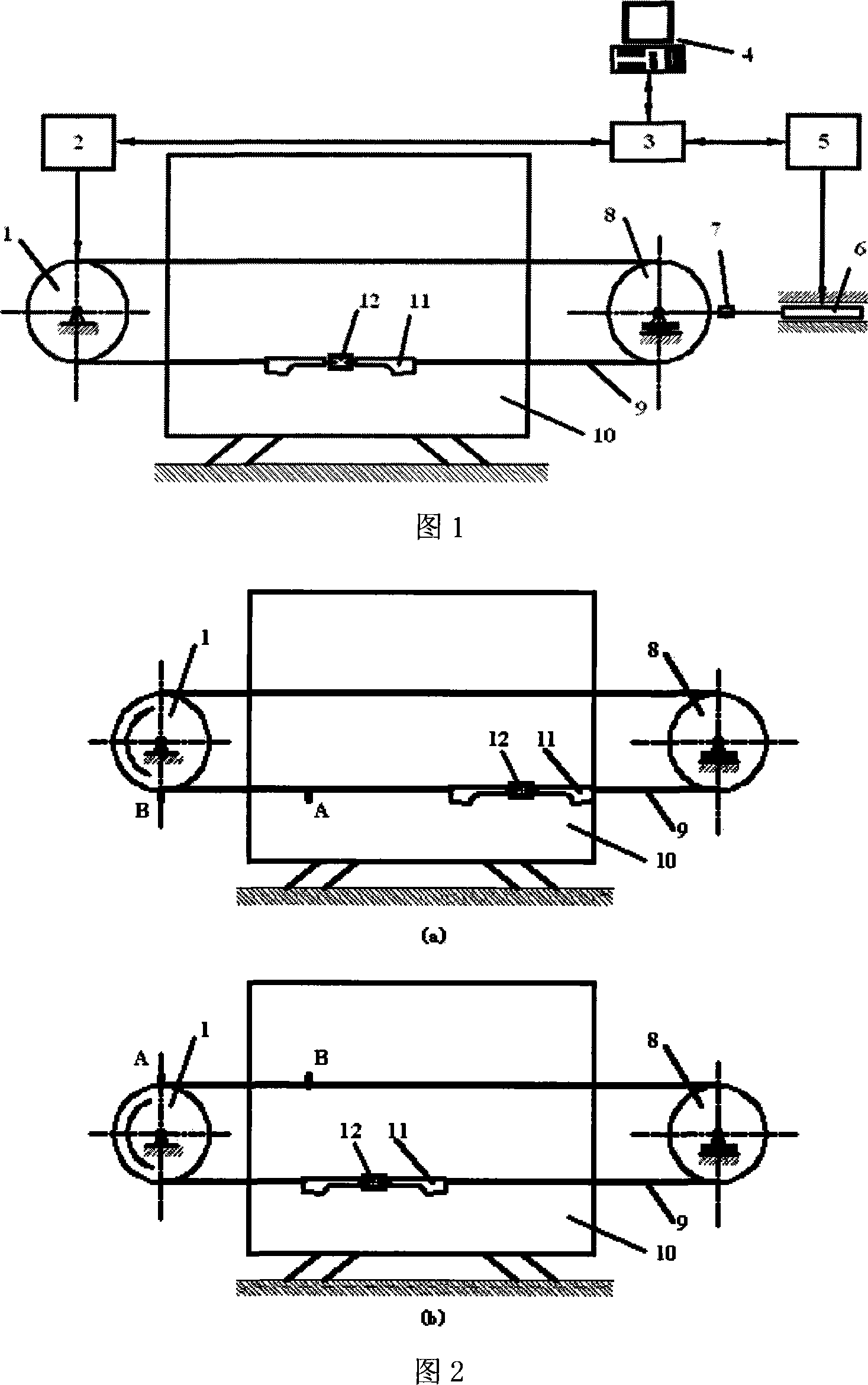
[0024] This embodiment is used for the independent bending fatigue test of steel wire ropes for elevators.

[0025]As shown in Figure 1, this embodiment includes: traction sheave 1, frequency conversion motor 2, data acquisition and control device 3, upper computer platform 4, hydraulic pump 5, hydraulic cylinder 6, tension sensor 7, tensioning wheel 8, and wire rope 9 , guide bracket 10, rope end device 11 and connection terminal 12, traction sheave 1 and tensioning sheave 8 are located at the two ends of the test bench respectively, guide bracket 10 is located between traction sheave 1 and tensioning sheave 8, and steel wire rope 9 is in turn Bypassing the traction sheave 1, the guide bracket 10 and the tensioning sheave 8, the two ends of the wire rope 9 are connected together through the rope head device 11 and the connecting terminal 12, the axle of the traction sheave 1 is connected with the output shaft of the variable frequency motor 2, and the tension The axle of the ...

Embodiment 2

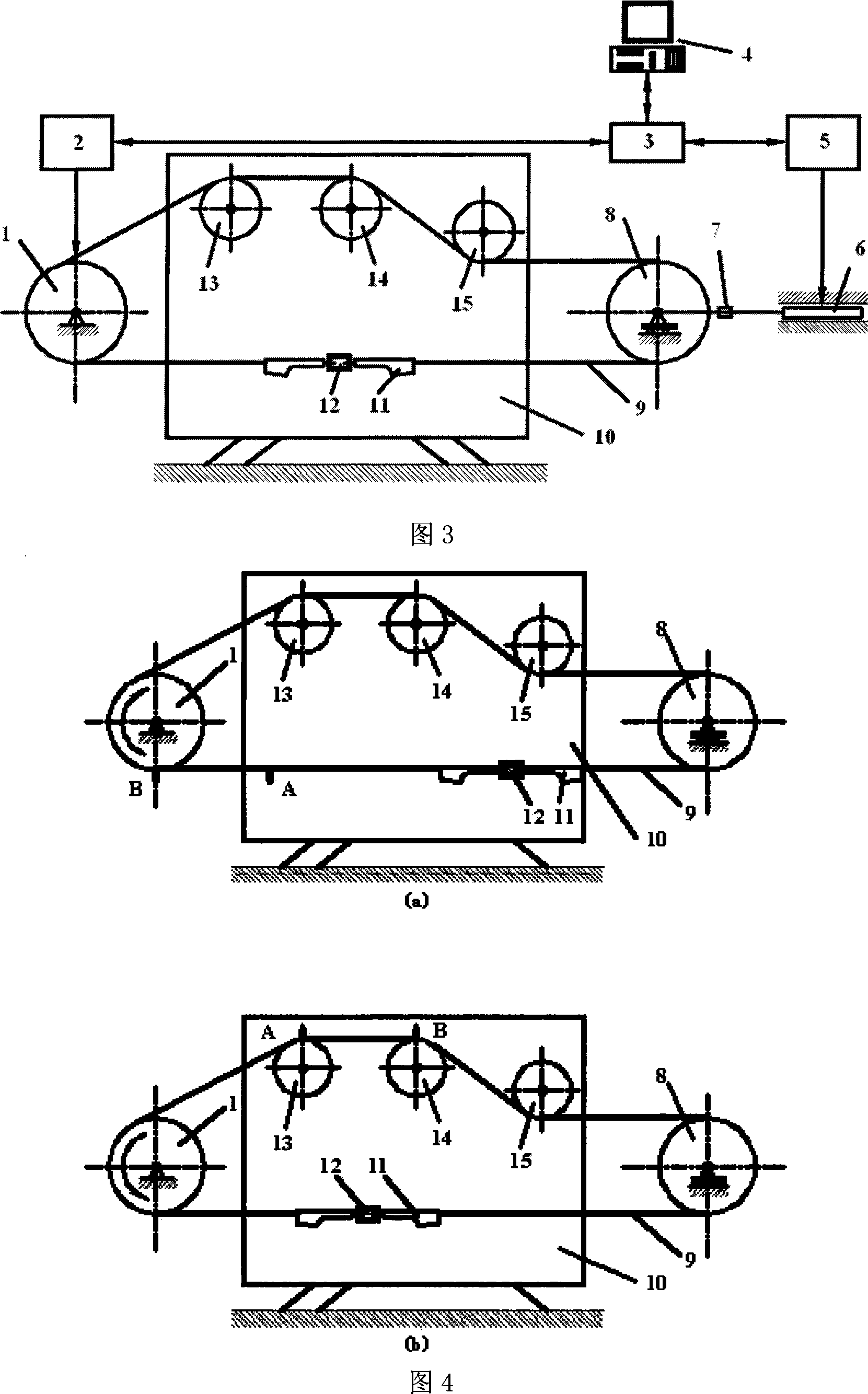
[0035] This embodiment is used for the same-direction combined bending fatigue test of steel wire ropes for elevators.

[0036] As shown in Figure 3, the overall structure of this embodiment is basically the same as that of Embodiment 1, wherein: the guide bracket 10 is provided with three guide wheels 13, 14 that are in the same vertical plane, have equal diameters and have semicircular rope grooves and 15, wherein the guide wheel 13 and the guide wheel 14 have the same height and are higher than the guide wheel 15, and the wire rope 9 stretches out from the traction wheel 1 and then bypasses the guide wheel 13 and the guide wheel 14 in the same direction, and then bypasses the guide wheel in the opposite direction. Wheel 15 is wound to tension pulley 8 again, and the lower edge of guide wheel 15 is concordant with the upper edge of tension pulley 8, guarantees that the wrap angle of steel rope 9 above tension pulley 8 is 180 °. The wheel grooves of the three guide wheels are...

Embodiment 3

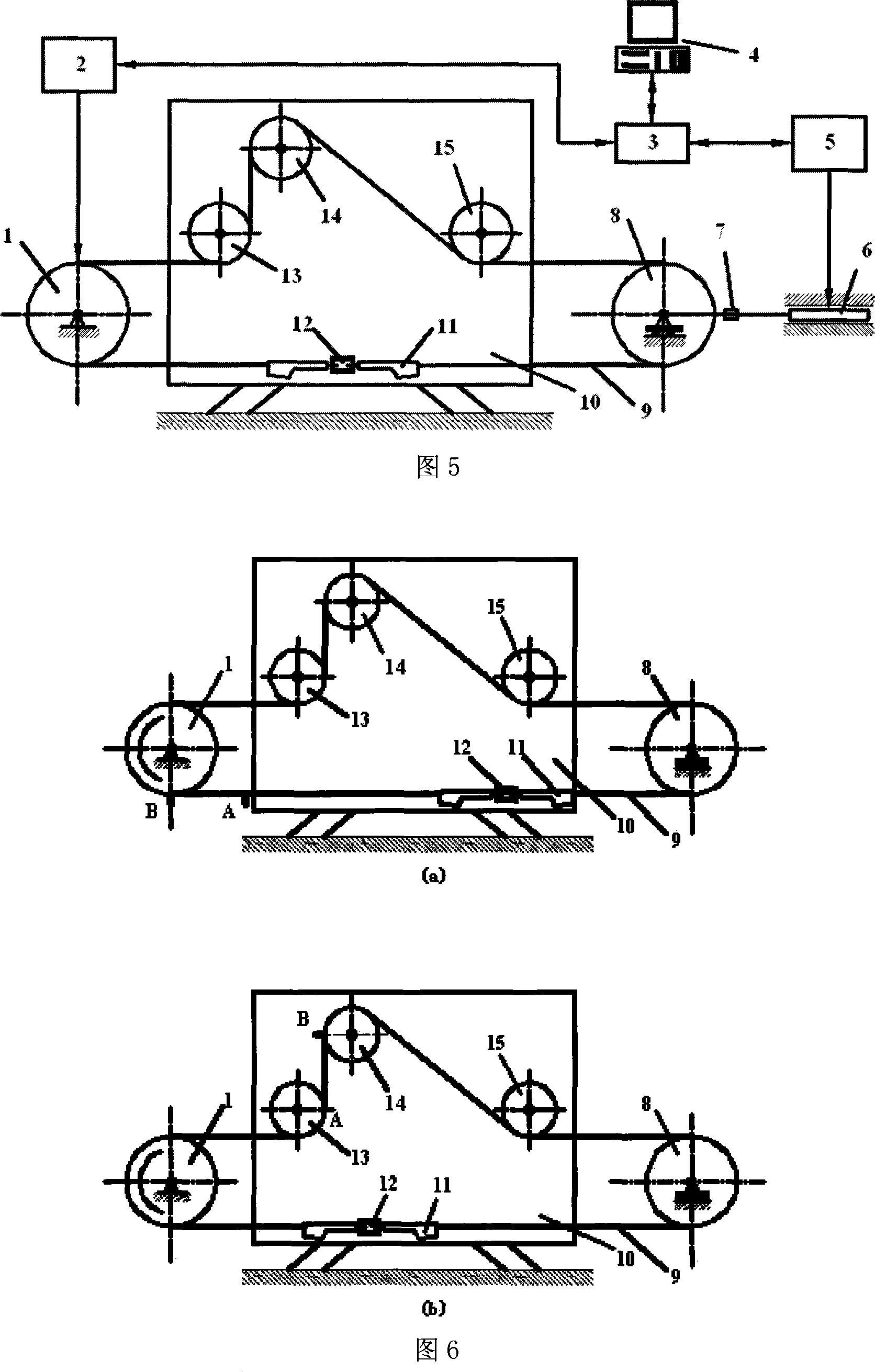
[0039] This embodiment is used for the reverse combined bending fatigue test of steel wire ropes for elevators.

[0040] As shown in Figure 5, the device structure of this embodiment is basically the same as the overall structure of Embodiment 1, wherein: the guide bracket 10 is provided with three guide wheels that are in the same vertical plane, have equal diameters and have semicircular rope grooves 13, 14 and 15, wherein the position of the guide wheel 14 is higher than that of the guide wheels 13 and 15. After the wire rope 9 stretches out from the traction sheave 1, it first goes around the guide wheel 13 in reverse, then goes around the guide wheel 14 in reverse, and then reverses To go around the guide wheel 15, and finally to the tension wheel 8, and its two ends are connected together by the rope head device 11 and the connecting terminal 12. The lower edge of the guide pulley 15 is flush with the upper edge of the tension pulley 8 to ensure that the wrapping angle o...


PUM


Abstract

A bending fatigue test platform of wire rope for an elevator in the field of mechanical technology comprises a traction wheel, a frequency-variable motor, a data collecting and control device, a host computer platform, a hydraulic pump, a hydraulic cylinder, a tension sensor, a tension pulley, a wire rope, a rope head device, a connection terminal and a guide support, wherein the traction wheel and the tension wheel are positioned on both ends of the test platform; the guide support is positioned between the traction wheel and the tension pulley; the wire rope is wound in the grooves of the traction wheel, the guide wheel of the guide support and the tension pulley; the shaft of the tension wheel is connected with the tension sensor; the tension sensor is connected with the hydraulic cylinder; the hydraulic cylinder is connected with a hydraulic pump; the frequency-variable motor, the hydraulic pump and the tension sensor are connected with the data collecting and control device; and the data collecting and control device is connected with the host computer platform, which is in charge of monitoring, recording and control. The invention can adjust the wrap angle, the bending state, the tension and the travel of the bending fatigue test of wire rope more flexibly.

Description

technical field [0001] The invention relates to a device in the field of mechanical technology, in particular to an elevator steel wire rope bending fatigue state test bench. Background technique [0002] As an important part of the traction elevator, the wire rope plays a vital role in the operation safety of the elevator. The movement of the wire rope in the elevator depends on the friction between the wire rope and the traction sheave groove, and due to the requirements of transmission and space constraints, there are certain guide wheels in the elevator suspension system, which makes the bending state of the wire rope very complicated. Therefore, it is of great practical significance to observe and study the bending fatigue state of steel wire ropes used in elevators to ensure the safe use of steel wire ropes. At present, there is no corresponding national standard for the fatigue test of steel wire ropes for elevators. The standard that can be referred to is the hoisti...

Claims


Application Information

Patent Timeline
Patent Type & Authority Applications(China)
IPC IPC(8): G01N3/34
Inventor 朱昌明张鹏胡晖张晓峰
Owner SHANGHAI JIAO TONG UNIV
Why Eureka
Try Eureka