Photolithography method and apparatus

a photolithography and photomechanical technology, applied in the field of photolithography methods and apparatuses, can solve the problems of short replacement cycle, short operation time of light sources, short replacement cycle, etc., and achieve the effect of extending the operation life and reducing the cost of photolithography methods and apparatus

Inactive Publication Date: 2005-11-17
FUJIFILM HLDG CORP +1
View PDF7 Cites 6 Cited by
  • Summary
  • Abstract
  • Description
  • Claims
  • Application Information

AI Technical Summary

Benefits of technology

[0008] The present invention has been developed in view of the circumstances described above, and it is an object of the present invention to achieve cost reductions in the photolithography method and apparatus, in which photoli

Problems solved by technology

This means a correspondingly longer operating time and shorter operation life of the light sources, resulting in shorter replacement cycle and higher

Method used


Image

  • Photolithography method and apparatus
  • Photolithography method and apparatus
  • Photolithography method and apparatus

Examples


Embodiment Construction

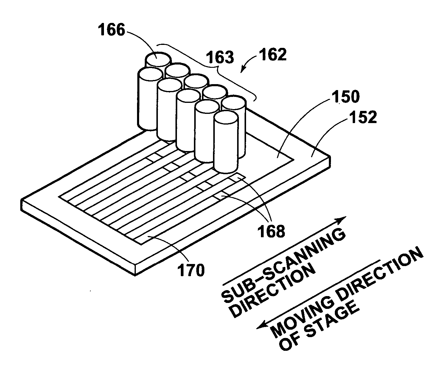
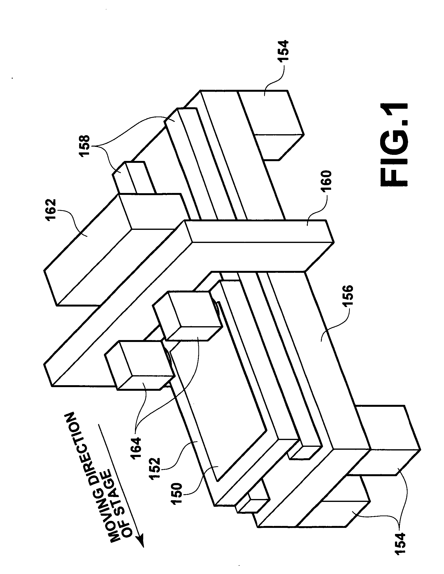
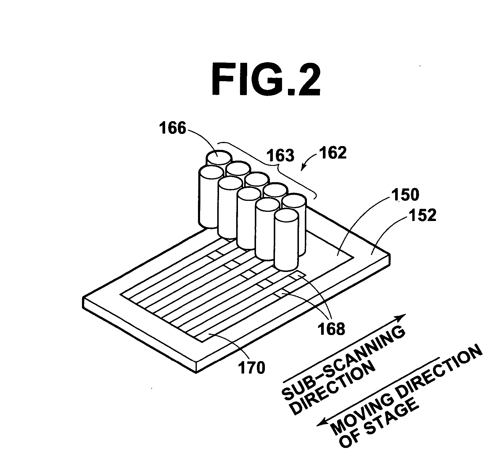
[0057] Hereinafter, an embodiment of the photolithography apparatus upon which a photolithography method of the present invention may be implemented will be described with reference to the accompanying drawings. The photolithography apparatus of the present invention has advanced features in the drive controlling method for the exposing light sources. But, the overall construction of the apparatus will be described first to provide an overview of the apparatus.

[0058] As shown in FIG. 1, the photolithography apparatus of the present embodiment has a plate-like moving stage 152 for holding a sheet-like photosensitive material 150 thereon by suction. Two guides 158 extending along the moving direction of the stage are provided on the upper surface of a thick plate-like mounting platform 156 which is supported by four legs 154. The stage 152 is arranged such that its longitudinal direction is oriented to the moving direction of the stage, and movably supported by the guides 158 to allo...


PUM


Abstract

In a photolithography method for performing photolithography with an exposing section that has a plurality of exposing head arrays arranged in the sub-scanning direction, cost reductions are achieved by extending the operation life of the exposing light sources and replacement cycles. Irradiation of the exposing light beams by the exposing head arrays is initiated or terminated on an array by array basis by drive controlling the exposing light sources constructed to output the exposing light beams, and if the irradiation coverage of an exposing head array is out of the photosensitive material, the laser modules are drive controlled such that the irradiation of the exposing light beams by the exposing head array is terminated.

Description

BACKGROUND OF THE INVENTION [0001] 1. Field of the Invention [0002] The present invention relates to a photolithography method and apparatus in which a photosensitive material is exposed with an exposing section comprising a plurality of exposing head arrays arranged in the sub-scanning direction, each of which having a plurality of exposing heads disposed in the main scanning direction. [0003] 2. Description of the Related Art [0004] Various types of photolithography machines are proposed, in which laser beams are modulated in accordance with image data using spatial light modulation devices, such as DMDs (digital micro-mirror devices) or the like, and a photosensitive material is exposed by the modulated laser beams. [0005] One such photolithography machine in which a photosensitive material is exposed by scanning the material with a plurality of exposing heads having spatial light modulation devices is proposed as described, for example, in Japanese Unexamined Patent Publication ...

Claims


Application Information

Patent Timeline
IPC IPC(8): G03F7/20B41J2/435B41J2/465H01J33/00
CPCG03F7/2053B41J2/465G03F7/70275G03F7/70291G03F7/20G03F9/00
Inventor HASHIGUCHI, AKIHIRO
Owner FUJIFILM HLDG CORP
Why Eureka
Try Eureka