Precision positioning method for rotating mould cutting roller

A technology of precise positioning and cutter roll, applied in rigid/semi-rigid container manufacturing, paper/cardboard containers, container manufacturing machinery, etc., to achieve the effect of convenience and error avoidance

Inactive Publication Date: 2008-07-16
姚福来
View PDF0 Cites 0 Cited by
  • Summary
  • Abstract
  • Description
  • Claims
  • Application Information

AI Technical Summary

Problems solved by technology

[0003] In order to overcome the problems of accuracy and reliability in the indirect positioning method of the existing die-cutter rollers, the present invention provides a simple precision positioning method for the rotary die-cutter rollers. The method reads the phase of the rotary die-cutter rollers directly precise positioning of the rotary die cutter roll

Method used


Image

  • Precision positioning method for rotating mould cutting roller
  • Precision positioning method for rotating mould cutting roller
  • Precision positioning method for rotating mould cutting roller

Examples


Embodiment Construction

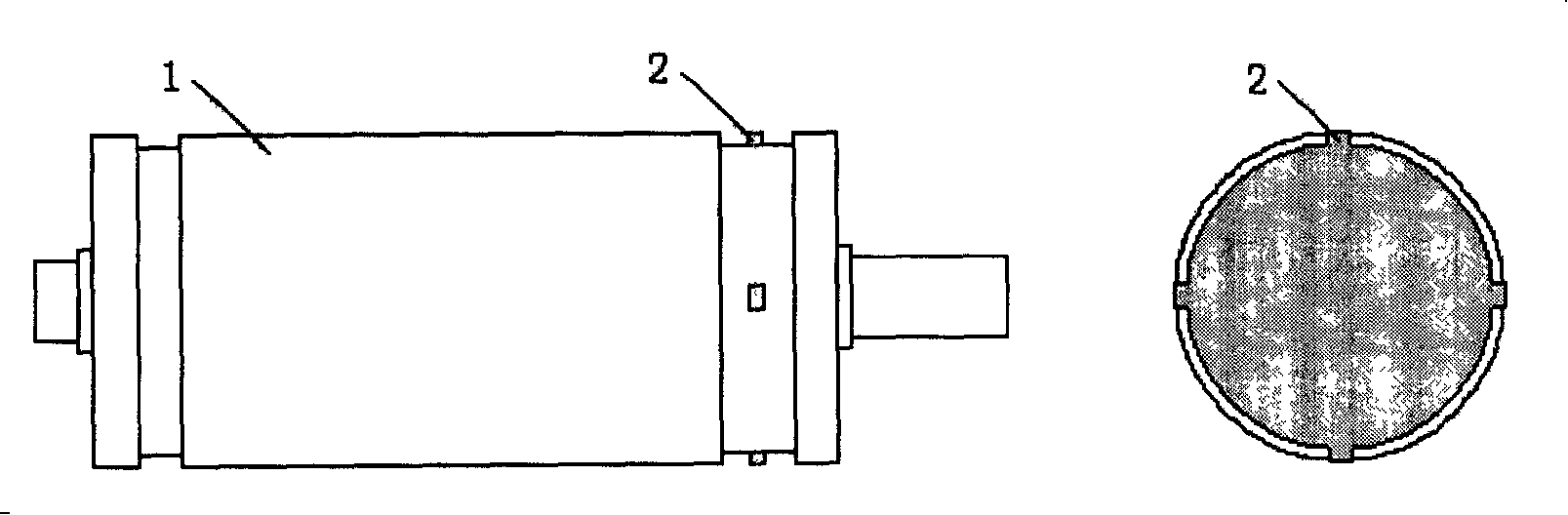
[0011] exist figure 1 Among them, there is a row of bosses (2) evenly distributed along the circumference on the die-cutting knife roller (1), and the number of bosses (2) is four in total. Using the inductive proximity switch to detect the arrival time of the bosses, it can be directly obtained The current position of the die cutter roll (1).

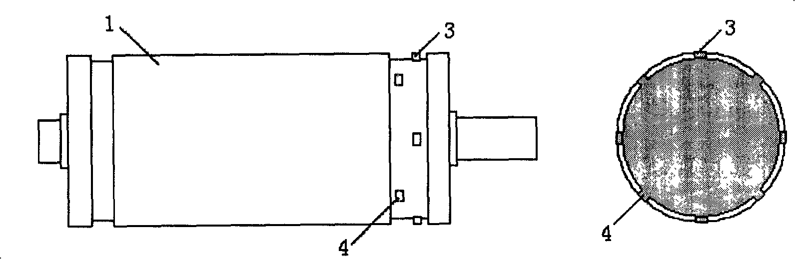
[0012] exist figure 2 Among them, there are two rows of evenly distributed bosses on the die cutter roller (1), one row is bosses (3), and the other row is bosses (4). The number of bosses in each row is four, and the die cutter There are eight bosses on the roller (1), and there is a certain distance between the two rows of bosses, and the bosses (3) and bosses (4) are staggered at a phase angle of 45° from each other, and the inductive proximity switch is used to detect them. The arrival time of a row of bosses can directly obtain the current position of the die-cutting knife roller (1). When the phase relationship between the ind...


PUM


Abstract

The invention relates to a precise positioning method of a rotation die cutter roll, which uses mark of the die cutter roll for positioning, while on the rotation die cutter roll, bosses for reading cutter roll position is processed. The position of the bosses can be directly read by a sensor, namely the position of the rotation die cutter roll is known. The bosses are averagely distributed along the same circle direction of the die cutter roll, or two lines of bosses can be averagely distributed with a certain staggered angle along two staggered circles.

Description

[0001] Technical Field The present invention relates to a precision positioning method, especially a precision positioning method for a rotary die cutter roller. Background technique [0002] Die-cutting process exists in a large number of production occasions such as adhesive products, cigarette packs, instant noodle bowl lids, packaging boxes, etc. Some are die-cut according to the printed pattern shape, and some are die-cut according to the designed shape. At present, mobile phones, MP3, digital cameras and other electronic products with large batches and fast updates require a large number of multi-layer or single-layer adhesive products for bonding between various parts, such as the bonding between the screen and the shell, the earpiece and the Bonding between cases, screen protectors, etc. Die-cutting methods include flat stamping die-cutting method and rotary die-cutting method. Because rotary die-cutting has great advantages in processing speed, it has gradually become...

Claims


Application Information

Patent Timeline
Patent Type & Authority Applications(China)
IPC IPC(8): B31B1/20B31B50/20
Inventor 姚福来
Owner 姚福来
Why Eureka
Try Eureka